
Emergency Stop Deceleration Shock and Holding Brake Sizing in Servo Rotary Actuators: Peak Impact (T2max), Dynamic Braking, and Safe Stop Compliance
Size emergency stop torque and holding brakes for servo rotary actuators. Compare T2max, SS1/STO and braking resistor power; use the engineering RFQ checklist.
When an automated machine trips a safety light curtain, trips an interlock switch, or triggers an emergency stop (E-stop), the drivetrain of a servo rotary actuator can experience a transient rise in mechanical stress, depending on the stopping method. Machine designers and procurement engineers routinely calculate nominal running torque (T_2N) and standard acceleration torque (T_2B or T_2acc) during station commissioning. Emergency deceleration can impose a higher transient load than routine indexing, so it needs a separate sizing check.
High-inertia multi-station dial plates, pneumatic clamping nests, and heavy tooling assemblies store rotational kinetic energy (E_k = 0.5 * J_total * omega²). When safety circuits cut power or drop a mechanical friction brake without coordination, the stopping path must absorb that energy over the actual measured stopping time. If the resulting deceleration shock torque exceeds the reducer's catalog emergency stop torque rating (T_2max or T_2NOT), gear teeth, couplings, and bearings may be overloaded. Exceeding a catalog limit requires engineering review; it does not predict an exact failure threshold.
Simultaneously, a persistent misconception across procurement and controls teams is that ordering a servo motor equipped with an internal electromagnetic brake solves emergency stopping requirements. A motor holding brake primarily maintains standstill. Limited emergency braking may be permitted by a particular brake manufacturer, but a static torque rating does not establish dynamic stopping capability.
This guide provides a mechanical, electrical, and procurement screening framework for sizing emergency stop torque, selecting braking architectures, and identifying the validation needed under functional safety standards (IEC 60204-1 and ISO 13849-1). If your machine station carries high inertia or vertical payloads, review our servo hollow rotary actuators and precision rotary indexing tables, or submit your CAD load parameters to our engineering team to discuss application sizing and the data needed for validation.
Technical review date: November 06, 2026. Global, English-language selection guidance for machine builders and technical buyers. Worked examples are calculations, not hardware tests or a declaration of machine compliance. Local adoption and applicable machine-specific standards must be checked separately.
1. Scope, Engineering Assumptions, and Mechanical Boundaries
This guide addresses the reducer, coupling, motor brake, and drive of a servo rotary table. The purchasing decision is whether the proposed combination can decelerate the load, absorb its energy, and then hold it under the specified failure conditions. These are separate requirements.
The initial calculation treats the load as rigid and assumes constant deceleration. Real backlash, torsional stiffness, control response, and fixture flexibility can increase peaks. Any shock multiplier below is an illustrative assumption to be replaced by supplier analysis or measured torque data, not a prescribed standard value.
On a balanced horizontal dial rotating about a vertical axis, gravity produces no driving torque about that axis. A tilted or horizontal-axis positioner can have gravity torque that changes with angle and direction. Include the most adverse payload position, process force, imbalance, and foreseeable loss of power or pressure.
Catalog symbols and event limits are manufacturer-specific. Do not transfer a planetary reducer's rating definitions to a strain-wave or cycloidal actuator without checking its manual. This article does not cover explosive atmospheres, liquid sloshing, or flexible multi-body systems. Those applications require a separate model.
2. Drivetrain Torque Taxonomy: Nominal, Acceleration, and Emergency Limits
2.1 Nominal Output Torque (T2N)
Nominal torque describes a defined speed, duty, temperature, and life condition. It is not an indefinite-load promise. Check the supplier's thermal and fatigue assumptions, lubrication, mounting orientation, and bearing load limits rather than assuming a universal service life.
2.2 Maximum Acceleration Torque (T2B or T2acc)
Acceleration torque covers a specified cyclic peak. Its permissible duration, repetition rate, and relationship to RMS torque must be read together. There is no universal multiplier between nominal and cyclic torque. Normal indexing and frequent protective stops belong in the duty calculation.
2.3 Emergency Stop Torque (T2max or T2NOT)
An exceptional-load rating may allow a higher output torque for a restricted number of events and duration. T2max can have a different meaning in another catalog, so ask the vendor to identify which rating covers your stop profile. Do not interpret it as the exact material breaking point.
Procurement rule: obtain the rated value, permitted event count, speed, duration, and post-event inspection requirements for the exact model. A quoted allowance of 1,000 events, where a manufacturer provides one, cannot be generalized to every rotary actuator. If routine light-curtain interruptions use the same stop, count them in the service duty instead of treating them as rare emergencies.
3. First-Principles Emergency Stop Torque Calculation
3.1 Mathematical Derivation
Use output-side quantities consistently for the gearbox output-load check. For table speed n in RPM, angular velocity omega in rad/s, stop time t in seconds, and output load inertia J_load in kg·m²:
omega = 2 * pi * n / 60
alpha = omega / t
J_load = J_dial + J_fixtures + J_output_components
T_inertia = J_load * alpha
For a solid circular plate, J_dial = 0.5 * m * R². For fixtures treated as point masses, use sum(m_j * r_j²); add each fixture's own centroidal inertia when it is significant. The parallel-axis method lets procurement compare different fixture layouts rather than choosing an actuator from total mass alone.
A conservative first screen, omitting helpful friction, is:
T_screen = K_A * (J_load * alpha + abs(T_external_adverse))
S_B = T_emergency_allowable / T_screen
Here external adverse torque includes the gravity or process torque that drives continued motion. Analyze both directions. K_A is an assumed allowance for unresolved dynamics, not a substitute for a transient model. Comparing T_screen with the applicable catalog limit is necessary but cannot alone establish a safe machine. Any additional design margin must be agreed for the application; 1.5 is not a universal compliance requirement.
The motor and drive need a separate input-side torque calculation, including motor rotor and input-stage inertia. Load inertia reflected to the motor is J_load / i², where i is the motor-to-output speed ratio. Conversely, motor inertia expressed at output speed is J_motor * i². Do not add motor inertia indiscriminately to the gearbox output load, or omit it from total stored-energy and motor braking calculations. Use the supplier's motoring and backdriving loss model.
3.2 The Deceleration Time Cliff
For fixed inertia and initial speed, ideal inertial torque varies as 1 / t. Changing a 250 ms ramp to 30 ms increases this component by 250 / 30 = 8.33. Whether the assembly exceeds a limit depends on its actual ratings and torque path; the ratio alone does not predict tooth failure.
Stopping travel matters as well. Under constant deceleration, theta_stop = omega * t / 2. Add travel during sensor, controller, drive, and brake response delays. A longer ramp can reduce mechanical torque while increasing travel toward a hazard, so both constraints must be resolved together.
4. Holding Brakes vs. Dynamic Braking: Size Both Functions
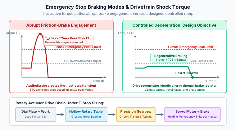
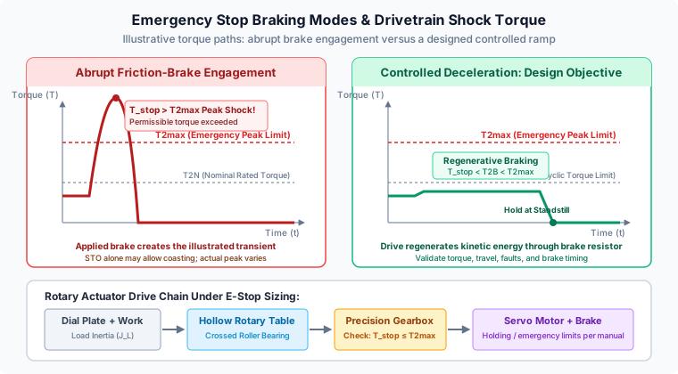
Conceptual torque paths, not measured traces. STO alone does not create the illustrated friction-brake spike. The controlled profile is a sizing objective, not an inherent SS1 guarantee.
4.1 How a Motor Holding Brake Works
A spring-applied electromagnetic holding brake engages when its coil is de-energized. Supplying its specified voltage releases the brake. Its principal task is to maintain standstill; it has mechanical engagement and release delays that depend on the brake and its suppression circuit.
Schneider Electric's holding-brake instructions distinguish service braking from permitted limited moving-load applications. Obtain the model's dynamic energy, speed, torque, and event-count limits. Unsupported claims about a fixed number of stops to failure or a universal wear percentage cannot support a purchase decision.
4.2 Dynamic Engagement and the Load Path
Applying a brake while moving may generate heat, wear, and torsional oscillation. A motor-side brake restrains the table through the coupling and reducer. An output-side brake provides a different restraint path, but an attached gearbox can still experience torque from the connected inertias and elasticity. A positioning clamp is not automatically a dynamically rated emergency brake.
4.3 Static Holding-Brake Torque Sizing
For a horizontal-axis positioner, calculate the maximum gravity moment over its travel. A simplified worst-case load is T_hold,out = m * g * e + abs(T_process), where e is the perpendicular center-of-gravity offset and g = 9.81 m/s². Include tooling and imbalance. Inertia does not create a static gravity moment, and a centered payload on a vertical rotation axis has a different holding requirement.
For preliminary selection through an intact drivetrain, use:
T_brake,motor,min >= S_H * T_hold,out / (i * c_hold)c_hold is an agreed conservative transmission allowance, not an assumed universal static efficiency. Confirm the vendor's load-transfer and backdriving model. For an illustrative output moment of 120 N·m, ratio 10, chosen margin S_H = 2, and assumed c_hold = 0.90, the screen calls for 2 * 120 / (10 * 0.90) = 26.7 N·m minimum motor-brake torque. A direct output brake with the same chosen margin would require 240 N·m. These are independent hypothetical holding inputs, not the horizontal dial example in Section 7.
Specify minimum available holding torque across temperature and wear, not only a nominal value. Ask about contamination, brake supply, engagement delay, inspection, and proof-test provisions. A larger motor brake cannot protect against a downstream coupling or gear failure. Where that failure is hazardous, the risk assessment must address a suitable independent restraint path.
5. Comparative Evaluation of Rotary Table Braking Architectures
The following six options have different holding, stopping, and energy functions. No generic stopping time or energy rating can be assigned without a model and load profile.
| Architecture | Intended function | Energy or response constraint | Drivetrain implication | Procurement evidence |
|---|---|---|---|---|
| Motor holding brake | Standstill holding; limited moving-load stops only if approved | Model-specific engagement delay and permitted friction work | Holds through coupling and gears | Minimum holding torque, emergency limits, event count |
| Drive regenerative braking with resistor | Controlled deceleration while the drive can generate torque | Motor current, DC bus, chopper, and resistor pulse capacity | Braking torque travels through gears | Torque-speed curve, pulse energy, stop sequence |
| Output pneumatic clamp or brake | Direct restraint; dynamic stops only with an explicit rating | Air-loss behavior, pressure, response, and friction work | Different restraint path; connected drivetrain still needs analysis | Static/dynamic distinction and loss-of-air behavior |
| Hydraulic disc or caliper brake | Direct holding or dynamic stopping as rated | Pressure availability, leakage, heat, and response | Does not automatically eliminate gearbox transients | Dynamic torque/energy curves and pressure-failure behavior |
| Mechanical stop with absorber | End-of-travel containment on limited-angle axes | Stroke, impact energy, mounting strength, rebound | Impact can load bearings, fixture, and gears | Absorber rating and structural load-path calculation |
| Motor terminal shorting | Electrical deceleration where supported by the motor/drive | Speed-dependent torque, winding heat, switching limits | Still acts through the drivetrain; little standstill restraint | Manufacturer-approved circuit and torque-speed data |
Motor terminal shorting differs from a DC-bus braking chopper, which switches a resistor. Neither feature should be assumed available after every electrical fault.
For a quotation review, send the load and proposed stop profile with the architecture you intend to use. Ask the supplier to identify missing ratings before comparing price.
6. Functional Safety Compliance: Stop Categories, SS1, STO, and SBC
The IEC 60204-1:2016+A1:2021 catalog record identifies the electrical-equipment standard and its scope. Global projects must check the locally adopted edition and relevant machine-specific requirements. Referencing a standard in an RFQ does not establish compliance.
6.1 Stop Category 0 and Safe Torque Off (STO)
Category 0 removes actuator power immediately; STO inhibits drive-generated torque and can support this category. STO does not itself provide mechanical deceleration, holding, or electrical isolation. A balanced table may coast; a gravity-loaded axis may continue moving or accelerate. Friction-brake application is a separate action, not an inevitable result of STO.
6.2 Stop Category 1 and Safe Stop 1 (SS1)
Category 1 uses powered deceleration followed by removal of actuator power. SS1 can implement that sequence with STO. Its variants and fault response must be checked in the selected drive's safety manual. SEW-EURODRIVE's restrictions explicitly state that SS1-t does not safety-monitor the ramp and can reach STO without successful deceleration after a fault.
Specify the intended ramp, available braking torque, energy path, and validated stopping time. An ordinary drive current limit is not automatically a certified safety torque limit. Controlled braking can reduce mechanical peaks, but neither a category name nor an SS1 setting guarantees the gearbox torque envelope or shortest safe stop. Category selection follows the machine risk assessment.
6.3 Safe Brake Control and Gravity-Loaded Axes
Where holding is necessary, coordinate brake engagement with motor torque removal using documented response times and the validated safety architecture. Safe Brake Control (SBC) addresses brake control; it does not itself prove that a mechanical brake develops the required holding torque. Do not assume a universal 50–100 ms overlap or a generic low-speed threshold.
ISO 13849-1:2023 provides a design methodology for safety-related control systems; it does not prescribe a single required performance level for this application. Record the risk-assessed function, required performance level, fault behavior, and validation evidence. Include power-loss and brake-failure cases, not just the commanded production stop.
7. Worked Numerical Example: High-Inertia Rotary Assembly Table
To demonstrate the mathematical sizing process, consider a hypothetical multi-station assembly dial. The geometry, catalog ratings, stop times, and shock multipliers below are illustrative, not measurements or specifications for a sold model.
7.1 Input Parameters and Machine Specifications
- Dial Plate Geometry: Solid aluminum dial, diameter
D = 600 mm(R = 0.30 m), thicknesst = 20 mm, material densityrho = 2,700 kg/m^3. - Fixtures and Workpieces: 8 stations carrying assembly nests and components, total tooling mass
m_fixtures = 16 kg, mounted at pitch radiusR_p = 0.22 m. - Operating Speed: Table rotational speed
n_table = 45 RPM. - Assumed Actuator Parameters: Servo hollow rotary table with reduction ratio
i = 10, output-side internal inertiaJ_table = 0.005 kg·m^2. Motor rotor and input-stage inertia are excluded from this output-load screen. - Assumed Gearbox Ratings:
- Nominal torque:
T_2N = 85 N·m - Max acceleration torque:
T_2B = 170 N·m - Emergency stop peak torque:
T_2max = 340 N·m
- Nominal torque:
7.2 Step 1: Calculate Mass and Moments of Inertia
Dial Plate Mass (m_dial):
V_dial = pi · R^2 · t = pi · (0.30 m)^2 · 0.020 m ≈ 0.00565 m^3m_dial = V_dial · rho = 0.00565 · 2,700 ≈ 15.27 kgDial Plate Moment of Inertia (J_dial):
J_dial = 0.5 * m_dial * R^2 = 0.5 · 15.27 · (0.30)^2 ≈ 0.687 kg·m^2Fixtures Moment of Inertia (J_fixtures):
J_fixtures = m_fixtures · R_p^2 = 16 kg · (0.22 m)^2 ≈ 0.774 kg·m^2Total Load Inertia at Output Table (J_total, equivalent to J_load above):
J_total = J_table + J_dial + J_fixtures = 0.005 + 0.687 + 0.774 = 1.466 kg·m^27.3 Step 2: Calculate Angular Velocity
omega_table = (2 pi · 45) / (60) ≈ 4.712 rad/s7.4 Step 3: Compare Deceleration Scenarios
Scenario A: Standard Normal Cyclic Deceleration (Delta t = 200 ms)
alpha_normal = (4.712 rad/s) / (0.200 s) = 23.56 rad/s^2T_normal = J_total · alpha_normal = 1.466 · 23.56 ≈ 34.54 N·mEvaluation: 34.54 N·m < T_2B (170 N·m). This inertial torque is below the assumed cyclic limit. Thermal duty, bearing loads, and drive capability still need checking.
Scenario B: Controlled Category 1 Emergency Stop (SS1, Delta t_stop = 80 ms)
alpha_estop,SS1 = (4.712 rad/s) / (0.080 s) = 58.90 rad/s^2T_inertia = 1.466 · 58.90 ≈ 86.35 N·mApplying the illustrative shock factor K_A = 1.25:
T_stop,SS1 = 86.35 · 1.25 ≈ 107.94 N·mSafety Factor Evaluation:
S_B = T_2max / T_stop,SS1 = (340 N·m) / (107.94 N·m) = 3.15Conclusion: Within the assumed torque limits. The torque (107.9 N·m) is well below T_2max (340 N·m) and even below standard acceleration torque T_2B (170 N·m). This is a screening result, not a damage-free guarantee. The 80 ms ramp is an input assumption; actual stopping time includes response delays and must be validated.
Scenario C: Abrupt Friction-Brake Engagement (Delta t_stop = 15 ms)
If power is instantly cut and an aggressive friction brake or mechanical hard stop halts rotation in 15 milliseconds:
alpha_estop,abrupt = (4.712 rad/s) / (0.015 s) = 314.13 rad/s^2T_inertia = 1.466 · 314.13 ≈ 460.5 N·mApplying the illustrative backlash rebound shock factor K_A = 1.35:
T_stop,abrupt = 460.5 · 1.35 ≈ 621.7 N·mSafety Factor Evaluation:
S_B = T_2max / T_stop,abrupt = (340 N·m) / (621.7 N·m) = 0.547 (FAIL: < 1.0)Conclusion: Exceeds the assumed permissible emergency torque. The peak torque (621.7 N·m) exceeds the assumed catalog limit (340 N·m) by approximately 83% (about 183% of the rating). The selection fails this screen; the calculation cannot predict whether or when a particular component will break. STO without an applied brake is not this 15 ms scenario.
8. Sizing the Dynamic Braking Resistor for Emergency Deceleration
ABB's Electrical Braking guide explains braking power, DC-bus storage, and chopper/resistor arrangements. Use the selected drive's actual thresholds and approved resistor combinations; supply voltage alone does not determine them.
8.1 Stored Energy
For the output load in Section 7:
E_load = 0.5 * J_load * omega²
       = 0.5 * 1.466 * 4.712² = approximately 16.27 J
This is the load-side energy. Add motor rotor and other rotating components at their own speeds for a system total, plus energy released by a descending gravity load. Account for losses and usable DC-bus absorption in the electrical model. Do not select a resistor from the output inertia alone.
8.2 Average Stop Power vs. Peak Mechanical Power
For ideal constant deceleration over 0.080 s, using only that load:
P_stop,avg = E_load / t = 16.27 / 0.080 = 203.4 W
P_mech,peak = T_inertia * omega_initial
            = 2 * E_load / t = approximately 406.8 W
Mechanical braking power falls from its initial peak to zero with speed. Thus 203.4 W is the average over the stop, not the peak. At one such stop per second, the load-only long-term average is approximately 16.3 W. These three values answer different sizing questions.
8.3 Resistor and Chopper Acceptance Checks
Obtain the approved resistance range and chopper current rating. Resistance must not fall below the drive's minimum, and an excessive value can limit energy dissipation. While the chopper conducts, resistor power is approximately V_bus² / R; switching duty and bus buffering make its pulses different from the mechanical power profile.
Check the resistor's pulse-energy curve, repetition interval, thermal mounting, ambient derating, and overload protection. Include repeated normal indexing as well as the rare emergency pulse. A nominal 50 W or 100 W label alone cannot establish suitability. Request the supplier's complete energy budget and response to a hot resistor, DC-bus overvoltage, or loss of supply.
9. Sizing, Procurement, and PO Acceptance Verification Checklist
Before releasing a purchase order or completing a factory acceptance test, assign an owner to each of these eight checks:
- Load definition: document geometry, fixtures, payload extremes, center-of-gravity offsets, orientation, and output/load vs. motor-side inertia. Include empty and fully loaded cases.
- Catalog limits: obtain nominal, cyclic, and exceptional torque definitions, allowed duration and event count, plus bearing and coupling limits for the quoted model.
- Torque and travel: compare both rotation directions, gravity quadrants, and worst-case ramps. State the chosen engineering margin and total stopping travel, including response delays.
- Holding vs. stopping: calculate worst static holding torque independently. Obtain minimum brake torque, permitted moving-load energy, wear limits, and any required independent restraint.
- Safety function: document the risk-assessed stop category, SS1 variant if used, required performance level, power-loss response, and validation responsibility. Do not substitute a software torque setting for a safety function.
- Electrical energy: provide motor/drive torque-speed capability, the complete regenerative energy budget, approved resistance, pulse rating, thermal protection, and overvoltage behavior.
- Mechanical load path: check the coupling at motor-side torque and the reducer/output restraint at their respective torques. Include shaft, fastener, fixture, and bearing capacity rather than applying an unexplained reduction multiplier twice.
- Acceptance evidence: record measured stop time/travel, brake engagement and release timing, load-holding checks, operating temperature, and the approved fault tests. Define inspection and replacement intervals and retain results with the machine file.
A useful FAT record states initial speed, payload configuration, measured delay, deceleration interval, brake condition, and the instrument used. Do not infer a measured output peak from a low-bandwidth motor-current log without considering ratio, losses, inertia, and torsional response. Passing a calculation is a reason to proceed to validation, not to skip it.
10. Frequently Asked Questions
What is the difference between acceleration torque (T2acc) and emergency stop torque (T2max / T2NOT)?
Acceleration torque applies to the specified cyclic duty. Emergency torque applies only under the manufacturer's stated exceptional-load conditions. Symbols, allowable duration, and lifetime event counts vary by model; T2max is not a universal breaking torque or a guarantee of 1,000 stops.
Can a standard servo motor holding brake dynamically stop a rotating dial table?
Do not use a holding brake as a routine service brake. Some models permit limited emergency braking within specified speed, energy, torque, and event-count limits. Obtain those limits in writing; a static holding-torque rating alone does not establish dynamic stopping capability.
How does emergency stop deceleration time affect gearbox torque?
For the same inertia and initial speed under constant deceleration, inertial torque is inversely proportional to stop time. Reducing 200 ms to 30 ms raises this component by 6.67 times. Compliance, gravity, friction, and brake response determine the actual peak.
Does Safe Stop 1 guarantee a safe stop on a high-inertia rotary table?
No. SS1 can support controlled deceleration followed by STO, but it does not automatically guarantee a gearbox torque limit, brake engagement, or stopping distance. SS1-t does not safety-monitor the ramp. Select and validate the complete function through the machine risk assessment.
When should an external output-table brake be considered?
Consider it when the risk assessment requires a holding path independent of gearbox or coupling integrity, or when process loads need direct restraint. A positioning clamp may be static-only. Specify dynamic torque, energy, response, and failure behavior before assigning it a stopping function.
How do you calculate braking resistor power for an emergency stop?
Energy divided by stop time is the average power during that stop. For ideal constant deceleration to zero, peak mechanical braking power is twice that average. Actual resistor pulses also depend on DC-bus voltage, resistance, chopper switching, losses, and other rotating inertias.
11. Sources and Technical Verification Notes
Source URLs and edition identities checked November 06, 2026. The public standard catalog pages establish publication scope and identity; they are not a substitute for the full normative text. The calculations in this article are reproducible illustrative analysis, not manufacturer test results.
- IEC 60204-1:2016+AMD1:2021, consolidated edition 6.1 — electrical equipment of machines, including emergency-stop and drive-system provisions.
- ISO 13849-1:2023, edition 4 — methodology for designing safety-related control systems; application-specific safety functions and required performance levels must be determined separately.
- Schneider Electric — Holding Brake Connection — service-brake restrictions and model-specific limits for moving-load brake applications.
- SEW-EURODRIVE — MOVIMOT flexible DSI safety restrictions, edition 02/2026 — coasting/gravity hazards and the unmonitored SS1-t ramp. Product-specific restrictions illustrate why the selected drive manual must be read.
- ABB — Technical Guide No. 8: Electrical Braking, revision C — braking torque/power, chopper/resistor energy paths, and dimensioning principles (printed pages 6–15).
No universal emergency-event count, shock factor, or brake wear rate is inferred from these sources. Obtain the selected gearbox, motor, brake, and drive manuals before approval. Recheck this guidance when those components, payloads, stop settings, or applicable standards change.
12. Review Your Rotary Table Deceleration Profile Before Ordering
A useful RFQ includes dial dimensions, fixture masses and radii, maximum speed, orientation, index duty, stopping-time and travel limits, and the intended safety sequence. Ask the actuator supplier for a documented mechanical sizing review and the controls integrator for machine-level safety validation.
- Compare servo hollow rotary actuators for through-bore routing and the required load capacity.
- Review rotary indexing tables and precision rotary tables against your torque, bearing, and positioning requirements.
- Contact our application engineering team with those inputs and the proposed brake/drive models to discuss sizing and the remaining validation evidence.
Author

Categories
Delta t = 200 ms)Scenario B: Controlled Category 1 Emergency Stop (SS1, Delta t_stop = 80 ms)Scenario C: Abrupt Friction-Brake Engagement (Delta t_stop = 15 ms)8. Sizing the Dynamic Braking Resistor for Emergency Deceleration8.1 Stored Energy8.2 Average Stop Power vs. Peak Mechanical Power8.3 Resistor and Chopper Acceptance Checks9. Sizing, Procurement, and PO Acceptance Verification Checklist10. Frequently Asked QuestionsWhat is the difference between acceleration torque (T2acc) and emergency stop torque (T2max / T2NOT)?Can a standard servo motor holding brake dynamically stop a rotating dial table?How does emergency stop deceleration time affect gearbox torque?Does Safe Stop 1 guarantee a safe stop on a high-inertia rotary table?When should an external output-table brake be considered?How do you calculate braking resistor power for an emergency stop?11. Sources and Technical Verification Notes12. Review Your Rotary Table Deceleration Profile Before OrderingMore Posts
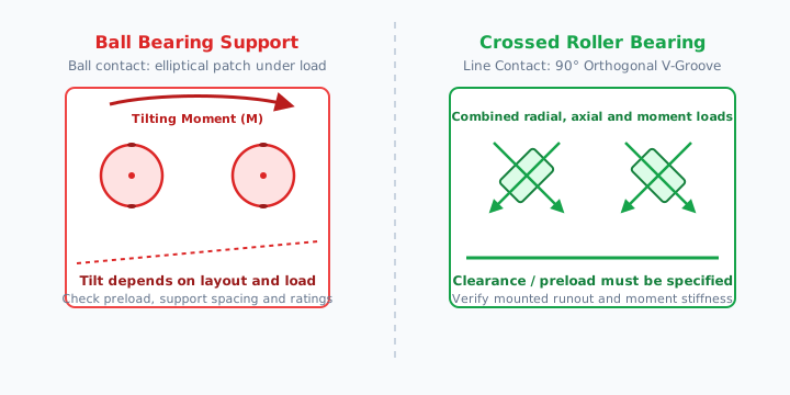
Crossed Roller Bearings vs. Ball Bearings in Servo Rotary Tables: Sizing for Tilting Moment, Runout, and TCO
Compare crossed roller vs. ball bearings for servo rotary tables. Calculate tilting moment, specify runout, and compare TCO with an engineering RFQ checklist.
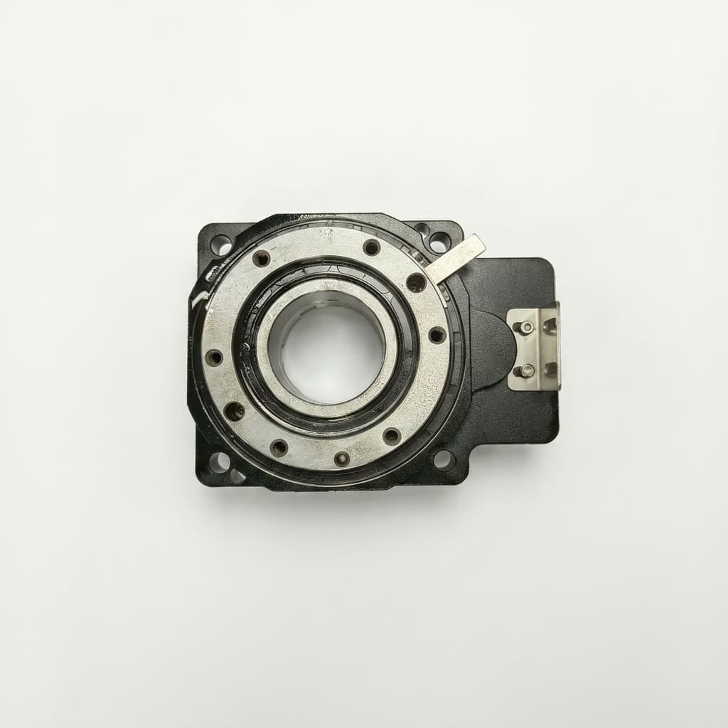
Battery-less vs. Battery-Backed Encoders in Servo Rotary Tables: A TCO Guide
Discover why procurement teams are switching to battery-less absolute encoders for servo rotary actuators. Compare TCO, maintenance costs, and integration requirements.

2026-W25 Servo Rotary Sourcing: New Compliance Gates & Sizing Safeguards
Week-25 buyer brief for servo hollow rotary tables: EU 12-month sanction extension, USTR forced labor duty proposals, pneumatic air compressor anti-dumping risk, and bore/load sizing rules.