
Crossed Roller Bearings vs. Ball Bearings in Servo Rotary Tables: Sizing for Tilting Moment, Runout, and TCO
Compare crossed roller vs. ball bearings for servo rotary tables. Calculate tilting moment, specify runout, and compare TCO with an engineering RFQ checklist.
When comparing crossed roller bearings vs. ball bearings in servo rotary tables, start with the load path, allowable tilt and duty cycle. A crossed roller ring is a strong candidate for a compact table carrying combined radial, axial and tilting loads. A properly sized angular contact ball bearing arrangement can also meet demanding rotary positioning requirements. Bearing architecture alone does not establish precision, life or value.
For servo hollow rotary tables and precision rotary tables, two quotes with the same drive torque and gear ratio may have different output-bearing arrangements. Ask for the bearing designation, combined-load limits and mounted accuracy evidence before comparing prices. If your load map is ready, request an engineering review with the force offsets and cycle profile.
Technical review: October 27, 2026. This is a catalog-based selection guide with hypothetical calculations, not a physical bearing test or customer case study.
Scope, Method, and Decision Assumptions
This guide is for global OEM procurement teams, machine designers and automation integrators specifying servo rotary actuators for assembly dials, inspection fixtures and similar indexing systems. It focuses on the main output support bearing, not the motor bearings or gearbox torque rating.
The method is to compare manufacturer guidance, calculate a transparent load example, and translate the result into an RFQ and acceptance checklist. No measured product stiffness, failure records or supplier quotations are supplied. Example assumptions are:
- Horizontal dial plate with a vertical rotation axis; other orientations require a new load map.
- Industrial index-and-dwell operation, with pressing normally performed while stationary.
- A balanced 400 mm dial and equally spaced fixtures, plus a separate eccentric press force.
- Example process targets of 0.012 mm axial face TIR and 0.010 mm radial TIR; these are requirements to validate, not guaranteed bearing performance.
- A project life target of 20,000 operating hours, distinct from calculated rolling-contact fatigue life and grease service intervals.
High speed, small-angle oscillation, vacuum, cleanrooms, food processing, large temperature swings and impact loads need application-specific manufacturer review. Confirm the actual center of gravity, acceleration, mounting stiffness and lubrication conditions before issuing a purchase order.
Key Executive Takeaways for Procurement & Engineering
- Calculate moment as well as axial load. A 30 N downward force at a 150 mm offset creates 4.5 N·m of tilting moment. Whether that is acceptable depends on the complete table's ratings and allowable deflection.
- Compare complete support arrangements. Crossed rollers support combined loads in one ring. Angular contact pairs can support moments through separated effective load centers; a single deep-groove bearing is a different comparison.
- Separate runout from stiffness. No-load TIR does not establish loaded angular deflection. Request both at defined mounting and temperature conditions.
- Check static load during dwell. Pressing a stationary dial requires a static capacity and stiffness check even when fatigue life during rotation is generous.
- Model TCO with your own evidence. There is no universal price premium or first-year payback. Include maintenance, quality loss and downtime assumptions explicitly.
Visualizing Bearing Architectures & Contact Mechanics
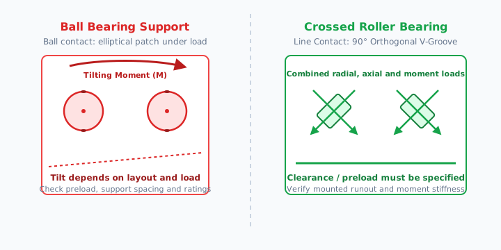
IKO's crossed roller overview explains how alternating rollers at right angles support combined loads in a compact ring. Ball contacts form finite elliptical patches under load; roller contact is also finite rather than an ideal mathematical line. Contact geometry alone cannot establish a fixed contact-area or stiffness ratio.
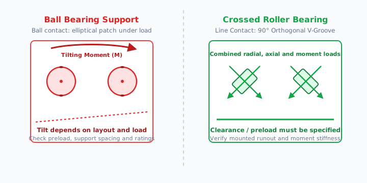
Figure 1: Conceptual load paths, not a dimensioned bearing section or test result. Both architectures deform under load. The diagram implies no runout rating, stiffness multiplier or service-life guarantee.
Detailed Bearing Architecture Comparison Matrix
Use this matrix to decide what to ask each supplier. The statements describe architectures; they are not product ratings.
| Selection dimension | Single crossed roller ring | Paired angular contact ball bearings | Deep-groove ball bearing support | RFQ implication |
|---|---|---|---|---|
| Contact geometry | Cylindrical rollers with alternating orientation | Balls with defined contact angle | Balls in grooved raceways | Obtain the bearing series and dimensions; geometry alone does not rate the table. |
| Combined loads | One ring can support radial, bidirectional axial and moment loads | Arrangement supports radial and axial loads; DB pairs can carry moments | Combined-load capability depends on the bearing and support arrangement | Request simultaneous-load limits, not separate maxima used together. |
| Moment stiffness | Depends on size, preload, rings and mounting | Depends on contact angle, effective support spread and preload | Depends on arrangement, clearance and housing | Compare moment-versus-tilt curves for the assembled table. |
| Axial envelope | Can provide a compact single-ring support | Pair spacing and retention affect height | Depends on the complete support layout | Compare drawings instead of assuming a fixed height advantage. |
| Hollow bore | Available in thin-section designs | Bore depends on the selected pair and retainers | Open-bore designs are possible | Check usable cable clearance in the assembled CAD model. |
| Preload | Specify clearance class and mounting requirements | Matched pairs can provide controlled preload | Clearance or preload depends on the design | Confirm friction, heat and installed preload. |
| Runout and shock | Requires accuracy and static-load verification | Requires accuracy and static-load verification | Requires accuracy and static-load verification | No architecture guarantees micron runout or immunity to brinelling. |
| Cost and service | Quote bearing, housing and replacement scope | Quote pair, retention and assembly work | Quote complete support, not an isolated commodity bearing | Compare equivalent specifications and documented service costs. |
NSK's angular contact bearing guide distinguishes back-to-back (DB) and face-to-face (DF) arrangements: effective load-center separation helps explain moment support. It does not establish that every ball-bearing table needs a taller package than every crossed roller table.
Housing and Bearing Mounting Matter
In a servo hollow rotary actuator, the load path includes the dial plate, output flange, bearing rings, housing, mounting bolts and machine base. Compliance or poor mounting at any interface can dominate the process error.
Request a section drawing and mounting instructions covering ring retention, mating-face flatness, bolt tightening and fits. A product exterior image cannot verify the internal bearing type, preload or moment capacity.
Mathematical Sizing Framework: Sizing for Tilting Moments
Drive torque rotates the dial about its axis. Tilting moment tries to tip that axis. Verify each against its own limit; a torque rating cannot substitute for an overturning-moment rating.
Step 1: Calculate Total Applied Tilting Moment
For forces producing moment in the same tilting plane, a conservative magnitude sum is:
M = sum(Fa × La) + sum(Fr × Lr)Here Fa is axial force in N, La its radial offset in m, Fr radial force in N, and Lr its height above the bearing reference plane in m. The result is N·m. For a general 3D load map, use moment vector = sum(position vector × force vector) and resolve the components. Opposing forces may cancel; torsion about the rotation axis belongs in the drive-torque check.
Separate gravity, indexing acceleration, dwell tooling forces and emergency-stop conditions. Balanced fixtures do not cancel an eccentric press force. Also verify whether a side force introduces an additional lever arm.
Step 2: Dynamic Equivalent Radial Load
For the THK cross-roller convention, the equivalent-load calculation is:
A  = Fr + 2M / dp
Pc = X × A + Y × Fa
Use forces in N, moment M in N·mm and roller pitch diameter dp in mm. The factor X multiplies the entire bracket, including the moment term. The catalog's factor branches are:
Fa / A ≤ 1.5:X = 1,Y = 0.45.Fa / A > 1.5:X = 0.67,Y = 0.67.- With
Fr = 0andM = 0, use the catalog's special pure-axial-load case rather than dividing by zero.
These factors belong to this catalog method, not all crossed roller products or ball-bearing pairs. Confirm the selected manufacturer's convention and preload treatment. See THK's nominal-life and equivalent-load guidance.
Step 3: Fatigue Screening and Its Limits
For a constant-load roller-bearing screen with temperature factor assumed to be 1:
Lscreen,h = [10^6 / (60 × n)] × [C / (fw × Pc)]^(10/3)C is the basic dynamic load rating in N, n the rotational speed in rpm, and fw an application load factor. Ball-bearing fatigue calculations generally use exponent 3, but a ball-bearing pair first needs its own reaction-load and rating calculation. THK's guidance gives load-factor ranges from 1–1.2 for smooth operation to 1.5–3 for excessive vibration or impact; selecting a factor does not approve an impact load.
Basic L10 denotes a fatigue estimate at 90% reliability under its stated conditions. The screen above includes an assumed load factor and is not a warranty or maintenance interval. Variable loads require a load spectrum weighted by revolutions. Distinguish rotating hours from calendar production hours, and check stationary pressing separately using static capacity and stiffness. Small-angle oscillation, lubrication, contamination and preload can control service life before calculated fatigue does.
Worked Sizing Example: 6-Station Automated Assembly Dial
Hypothetical, reproducible input set; no commercial actuator model or measured failure is represented. Consider a balanced 400 mm aluminum dial of mass 5.1 kg with six equally spaced 1.2 kg fixtures. A 180 N press acts at a 160 mm radius while the dial is stationary.
Calculate the Dwell Load
Gravity force = (5.1 + 6 × 1.2) × 9.81 = 120.663 N
Peak axial force = 120.663 + 180 = 300.663 N
Tilting moment = 180 × 0.16 = 28.8 N·m = 28,800 N·mm
The symmetric gravity load has no net tilting moment in this idealized layout. Actual unbalanced workpieces change that result. A 50 N radial side force is assumed to act in the bearing plane, so it adds no further tilting moment here.
Illustrate the Equivalent-Load Arithmetic
Assume a hypothetical crossed roller ring with dp = 95 mm and C = 16,800 N. For illustration only, apply the peak load to the dynamic-load expression:
A = 50 + 2 × 28,800 / 95 = 656.316 N
Fa / A = 300.663 / 656.316 = 0.458
X = 1; Y = 0.45
Pc = 656.316 + 0.45 × 300.663 = 791.614 N
If that same load were maintained during continuous rotation at 30 rpm, with fw = 1.4, the simplified fatigue screen would give approximately 4.79 million hours. That large mathematical result demonstrates why fatigue arithmetic alone cannot select this table. It does not establish actual bearing life, a permissible press load or loaded runout.
Decision: the actual press acts during dwell, so approval remains open until the supplier provides the static rating, combined-load safety check and mounted moment stiffness. A ball-bearing alternative cannot be declared failed from its dynamic rating alone; its arrangement, reaction loads, static capacity and stiffness are also needed. No failure time, contact stress or micrometer deflection is inferred from this example.
RFQ Sizing Reference Matrix
Frame size alone does not establish bearing capacity. Use the same six gates for each candidate rotary indexing table, regardless of bearing architecture:
| Gate | Buyer input | Supplier evidence | Acceptance decision |
|---|---|---|---|
| Load path | Axial and radial forces, offsets, dial orientation | Section drawing and bearing designation | Confirm the main support and all force lever arms. |
| Static capacity | Peak dwell and shock loads | Static rating, equivalent-load method and required safety margin | Approve the combined peak load, not isolated maximum ratings. |
| Stiffness | Maximum allowable tool-point displacement | Mounted moment-versus-tilt data and interface conditions | Convert angular tilt to displacement at the actual tool radius. |
| Accuracy | Axial/radial TIR budget and measurement radius | Assembled-table inspection method and report | Compare equal load, speed and temperature conditions. |
| Fatigue and lubrication | Revolutions, load spectrum, dwell and environment | Application life calculation, preload assumptions and lubrication plan | Separate fatigue estimates from service and grease intervals. |
| Integration and cost | Bore, envelope, servo interface and ownership period | CAD model, like-for-like quote, spares and replacement scope | Approve mechanical fit and evidence-based TCO together. |
For example, an assumed tilt limit of 0.05 mrad at a tool radius of 160 mm permits 160 × 0.00005 = 0.008 mm displacement. This is an error-budget conversion, not predicted performance. The bearing, housing and base must collectively meet the requirement.
How to Measure and Specify Runout: Static vs. Operational
A useful requirement states the datum, indicator position, applied loads, rotational speed, temperature and mounting conditions. No-load geometric TIR and loaded compliance are separate measurements.
Radial Runout
Measure a defined locating pilot or ground bore through a full revolution, relative to a stable base datum. Record indicator resolution and peak-to-peak reading. Surface form, eccentricity and setup error can contribute; this is not automatically a pure measurement of bearing axis error. Use a safe manufacturer-approved slow-rotation method.
Axial Face Runout and Loaded Tilt
Measure the mounting face at a specified radius through a full revolution. Then perform a separately defined loaded-deflection test, distinguishing rigid-body tilt from local plate or housing bending. A stationary loaded tilt reading is not interchangeable with full-revolution face TIR.
An example RFQ clause, to adapt to the process budget, is: “Axial face TIR ≤ 0.012 mm at a measurement radius of 160 mm, under no tooling load, at the agreed inspection speed and stabilized temperature. Separately measure angular deflection under a 28.8 N·m dwell moment; record the load direction, mounting bolt condition and acceptance limit agreed before testing.” These example values are not catalog ratings or a claim of compliance with a particular test standard.
Failure Modes When Either Bearing Arrangement Is Undersized
Excessive loads or poor mounting can cause elastic tilt, permanent raceway indentation, preload changes, fatigue damage, heat or abnormal vibration. These risks apply to both roller and ball bearings. The sequence and timing depend on the complete design and operating conditions.
Investigate measured runout changes, temperature, lubrication condition and mounting integrity before attributing servo alarms to a bearing. A contact-stress estimate requires bearing geometry and load distribution; drive torque and frame size alone cannot supply it.
TCO: Compare the Premium Against Documented Operating Costs
Over an agreed ownership period, compare:
TCO = purchase + installation + planned maintenance + spares
      + expected downtime cost + quality/rework cost
Hypothetical USD example, not supplier quotations: option A costs $620 and option B costs $890, a $270 premium. If all other costs are equal and downtime costs $150 per hour, B must avoid more than 270 / 150 = 1.8 hours over the chosen period to recover its purchase premium. Two documented avoided hours would be worth $300, leaving a $30 advantage before discounting and other differences.
This is a break-even threshold, not evidence that either bearing architecture will avoid downtime. Ask for service history or a validation test before assigning a failure probability. Compare taxes, freight, warranty, availability and replacement labor consistently across global quotes. If both arrangements meet the same load and accuracy requirements, the lower-cost package may offer better value.
Procurement & Engineering Verification Checklist
Before releasing a PO for a servo rotary table, confirm:
- Load map: record mass, CG, force directions and offsets for indexing, dwell and emergency stop.
- Bearing identity: obtain the main bearing series, arrangement, clearance/preload and combined-load limits in writing.
- Pitch diameter and factors: obtain
dpand the catalog method used for equivalent-load calculations. - Static approval: request a peak-load safety check; keep missing static capacity or stiffness as an open approval item.
- Mounted precision: specify radial/axial TIR, tool radius, temperature, datums and loaded-deflection acceptance conditions.
- Mechanical integration: confirm usable hollow bore, flange interfaces, bolt requirements, motor adapter and coupling ratings.
- Life and lubrication: request the load spectrum, fatigue calculation and environment-specific grease/seal maintenance plan; do not assume 20,000-hour grease life.
- Commercial comparison: include spares, replacement labor, validation evidence and downtime assumptions over the same TCO period.
Frequently Asked Questions
Why do crossed roller bearings handle tilting moments in a compact table?
Alternating cylindrical rollers at 90 degrees support radial, axial and moment loads in one ring. Their line-contact geometry can provide a compact, stiff support, but there is no universal stiffness multiplier over ball bearings. Compare the specific bearing, preload and housing.
How do I calculate the tilting moment on a servo hollow rotary table?
For loads acting in the same tilting plane, add axial force times radial offset and radial force times height above the bearing plane. A 180 N press force at 0.16 m creates 28.8 N·m. For general loading, resolve the force-moment vectors and separate tilting moment from drive torque.
What runout should I specify for a precision servo rotary table?
Derive the allowable runout from the process error budget. Specify radial and axial TIR, measurement radius, speed, temperature, mounting conditions and applied load. Bearing type alone does not establish a runout value; verify the assembled table and loaded deflection separately.
Can angular contact ball bearings match the performance of crossed roller bearings?
Yes, a properly selected angular contact arrangement can meet a rotary table specification. Back-to-back pairs support moment loads through their effective load-center separation. Compare measured stiffness, speed, envelope and preload; neither architecture is always superior.
What happens if a rotary table exceeds its allowable tilting moment rating?
Possible outcomes include excessive elastic tilt, loss of positioning accuracy, permanent raceway indentation or fatigue damage. The outcome depends on load magnitude, duration, static capacity and mounting. Exceeding a catalog limit does not establish a particular failure time.
How should I compare bearing configurations on total cost of ownership?
Compare like-for-like quotations, installation, maintenance, spares, quality losses and expected downtime over the same period. A higher purchase price is justified only by documented benefits; do not assume a fixed price premium or automatic first-year payback.
Sources and Technical Verification Notes
Reviewed October 27, 2026. These manufacturer references support the stated architecture and calculation methods. They do not certify the hypothetical inputs, prices, assembled-table tolerances or service life in this guide.
- IKO International — Crossed Roller Bearings: alternating roller orientation, combined-load support and compact bearing families.
- THK — Nominal Life and Dynamic Equivalent Radial Load: equivalent-load factors, fatigue framework, load factors and lubrication/oscillation limitations. Use the selected product's current rating and mounting instructions.
- NSK — Angular Contact Ball Bearings: matched DB/DF arrangements, effective load centers and moment support.
The worked numbers are calculations from explicitly assumed inputs. No physical test, customer outcome, universal cost premium or manufacturer-specific table rating is claimed.
Review Your Rotary Table Load Map Before Ordering
If your station carries off-center tooling, an assembly dial or intermittent pressing forces, compare complete support designs against the same load and error budget. A crossed roller ring can simplify a compact design; an approved angular contact arrangement can also be a suitable choice.
Contact our engineering team with dial diameter, payload/CG, force offsets, index cycle and allowable tool-point displacement to discuss a bearing and CAD review. Explore hollow rotary actuators and precision rotary tables with these requirements in hand.
Author

Categories
More Posts
Arc-min vs. Arc-sec in Servo Rotary Actuators: A Backlash Procurement Guide
Compare arc-min vs. arc-sec backlash in servo rotary actuators, calculate radius error, and request the right precision spec before you issue the RFQ.
Battery-less vs. Battery-Backed Encoders in Servo Rotary Tables: A TCO Guide
Discover why procurement teams are switching to battery-less absolute encoders for servo rotary actuators. Compare TCO, maintenance costs, and integration requirements.
Direct Drive vs Servo Hollow Rotary Tables: A Procurement and TCO Comparison
Direct Drive Rotary vs Servo Hollow Rotary Tables for precision indexing: compare backlash, inertia, tuning effort, lead-time risk, and TCO before RFQ.