
Torsional Stiffness, Resonant Frequency, and Dial Plate Settling Time in Servo Rotary Actuators: Sizing for Vibration-Free Indexing Throughput
Size servo rotary actuators for torsional stiffness, natural frequency, and settling time. Compare drive options and prepare a loaded-motion acceptance RFQ.
When machine builders and automation engineers select servo hollow rotary actuators for multi-station dial tables, indexing carousels, and vision inspection platforms, sizing calculations typically focus on two catalog parameters: continuous torque and gear backlash.
Torque and backlash checks alone do not establish cycle time. Drivetrain compliance and resonant settling vibration can delay a station even when motor torque and static positioning specifications are adequate.
For an illustrative cycle, a 90-degree index might take 250 milliseconds while the dial plate needs another 150 milliseconds to remain inside its process tolerance. The resulting 400-millisecond positioning interval must be budgeted before dispensing, vision inspection, or pressing can begin. These are assumed timing inputs, not measured production results or an industry-wide throughput claim.
The core takeaway: Specifying "zero backlash" does not prevent dial plate vibration. Backlash is static clearance; torsional stiffness (K_t, measured in N·m/arcmin) dictates the dynamic spring constant of the drivetrain. When driving a high-inertia load, an actuator with low torsional rigidity creates a low mechanical resonant frequency (f_r), capping the servo drive's tuning bandwidth and extending settling times. To achieve high-throughput indexing, engineering teams must size the mechanical natural frequency against the required motion profile before locking in a purchase order.
Published and content/source review: November 9, 2026. Scope: Global, English-language engineering guidance for electrically driven servo rotary actuators, dial tables, and hollow-shaft indexing platforms. The calculations are preliminary linear-model screens, not product ratings, measured hardware results, or machine acceptance certification. They omit higher structural modes, nonlinear friction, thermal drift, and controller-specific behavior unless stated.
Preparing a purchase specification? Start with the engineering and procurement checklist, then request an application review with your load inertia, index angle, motion time, and permitted residual motion.
Key Conclusions for Procurement & Engineering Teams
- Backlash and stiffness are distinct physical properties. A zero-backlash strain wave (harmonic) or preloaded planetary gearhead can still possess low torsional stiffness. Under high-inertia loads, gear compliance acts as a mechanical spring that stores and releases kinetic energy during deceleration.
- Settling time dictates real-world machine throughput. If a dial table requires 250 ms to index and 150 ms to settle within a
± 10 μminspection tolerance, the effective move time is 400 ms. The improvement from a stiffer transmission or a different motor depends on which constraint limits the actual machine. - Mechanical modes constrain servo bandwidth. For the ideal two-mass model, the motor-side anti-resonance is
f_ar = sqrt(K_t_rad / J_L) / (2π), using output-referred stiffness in N·m/rad. Actual bandwidth requires measured frequency response and adequate stability margins. - Drive notch filters have physical limitations. Software notch filters and input shapers can suppress resonance at a fixed frequency. However, when dial table inertia fluctuates due to workpiece loading and unloading, the resonant frequency shifts, degrading filter effectiveness.
- Direct drive removes gearbox compliance. Direct drive rotary stages remove a transmission stage, but the hub, dial plate, mounting joints, and frame remain elastic. Compare loaded settling traces rather than choosing an architecture from a universal millisecond threshold.
Visualizing Drivetrain Compliance, Resonance, and Settling
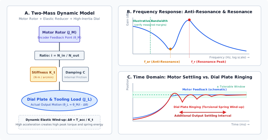
The diagram below illustrates the fundamental mechanics governing rotary table vibration: the two-mass physical model, the resulting frequency response (Bode plot) showing anti-resonance and resonance nodes, and the time-domain disparity between motor encoder position and actual dial plate settling.
The Physics of Torsional Compliance: Why Motors Settle While Dials Ring
To understand why a dial table oscillates, the electromechanical drivetrain cannot be modeled as a single, infinitely rigid body. A useful first approximation is a two-mass spring system; flexible plates and frames can require additional masses and modes:
- Mass 1: The motor rotor inertia (
J_M) and motor shaft. - The Spring: The flexible transmission element with torsional stiffness (
K_t) and viscous internal damping (C), encompassing the planetary gears, cycloidal pins, strain wave flexspline, output bearings, and shaft couplings. - Mass 2: The load mass moment of inertia (
J_L), representing the rotating dial table, fixture nests, pneumatics, and workpieces.
Drivetrain Elastic Deflection
When the motor applies an acceleration or deceleration torque (T), the compliant transmission twists by an elastic angle (Δ θ):
Δθ = T / K_tWhere:
Δ θis the elastic deflection angle in arcminutes (or radians).Tis the transmitted dynamic torque inN·m.K_tis the torsional rigidity of the actuator inN·m/arcmin. Match the angle unit to the stiffness unit; for a nonlinear torque-angle curve, use its local slope for small oscillations and the full piecewise torque-angle relation for larger deflections. The Harmonic Drive CSF/CSG catalog, p. 50 shows why a single spring rate may not describe the full torque range.
If an indexing table requires 120 N·m of peak deceleration torque to stop a dial plate, and the selected actuator has a torsional stiffness of 15 N·m/arcmin, the drivetrain twists elastically by:
Δ θ = (120)/(15) = 8.0 arcminutes
Eight arcminutes corresponds to 0.133 degrees. On a dial table with a tooling radius of 350 mm, an angular deflection of 8.0 arcmin translates to a tangential linear deflection at the outer fixture nest of:
Deflection = R × Δθ_rad = 350 mm × (8.0 × 2π / 21600) ≈ 0.814 mm (814 μm)
When the motor stops driving, this mechanical deflection does not instantly vanish. The stored potential strain energy in the transmission (E_p = (1)/(2) K_t,rad Δ θ_rad^2, using radians and N·m/rad) acts as a spring, discharging into the load inertia (J_L) and causing the dial plate to bounce back and forth until internal mechanical damping dissipates the energy.
Anti-Resonance and Mechanical Resonant Frequencies
In frequency-domain control analysis, the two-mass system produces two critical frequency nodes that appear on the servo drive's Bode plot:
1. Anti-Resonance Frequency (f_ar)
The anti-resonance frequency represents the natural frequency of the load mass oscillating on the spring while the motor rotor is held fixed:
f_ar = (1 / (2 × π)) × sqrt( K_t_rad / J_L )Note: In this formula, K_t must be converted to N·m/rad. Since 1 arcmin = (π)/(180 × 60) ≈ 2.90888 × 10^-4 rad, the stiffness in N·m/rad is K_t (N·m/arcmin) / (2.90888 × 10^-4) ≈ K_t × 3437.75.
In the ideal undamped motor-speed/torque transfer function, f_ar is a response zero. Real damping softens this dip. This does not mean the load is motionless. Beckhoff's two-mass resonance explanation distinguishes the motor-side response from the motion at the load.
2. System Resonance Frequency (f_r)
The mechanical resonance frequency represents the combined oscillation mode where the motor rotor and the load rotate in opposite directions (antiphase):
f_r = (1 / (2 × π)) × sqrt( K_t_rad × ( (1 / J_L) + (1 / (i² × J_M)) ) )Where:
J_Lis the actual load inertia at the gearbox output (kg·m^2).J_Mis the motor rotor inertia (kg·m^2).iis the gear reduction ratio (N_in / N_out).
Here K_t,rad and J_L are output-referred, while i^2 J_M is the motor rotor inertia referred to the output. Equivalently, input-referred load inertia is J_L/i^2. Include gearbox inertia when significant. For positive finite inertias, this ideal elastic mode lies above f_ar; its phase behavior depends on damping, feedback location, and the chosen transfer function.
The Closed-Loop Bandwidth Constraint
A low mechanical mode often requires reduced gains, but there is no universal bandwidth-to-anti-resonance ratio that certifies stability. Kollmorgen's advanced servo-tuner documentation gives one low-frequency example with a 30 Hz anti-resonance and approximately 15 Hz closed-loop bandwidth. That is a controller example, not a rule for all drives.
Use a measured plant response to set gain and phase margins. Record the feedback location, controller sampling, filters, and payload during identification. Increasing gains without checking these conditions can excite oscillations or cause drive faults; overly conservative gains can extend the approach to the final position. A frequency calculation therefore screens mechanical risk but cannot predict closed-loop settling time by itself.
Worked Sizing Comparison: Inertia and Stiffness Sensitivity
The following hypothetical dial table makes the arithmetic reproducible. Its geometry, density, stiffness inputs, and timing targets are assumptions, not a customer case study or a comparison of tested products. A drive architecture cannot be assigned a stiffness or settling time without an exact model and installation.
Application Baseline Specifications
- Mechanism: 8-station rotary indexing carousel.
- Dial Plate Geometry: Solid 6061-T6 aluminum disc, diameter
D = 600 mm(R = 0.3 m), thicknesst = 15 mm. - Workpiece Fixtures: 8 aluminum fixture nests with parts, each weighing
0.75 kglocated at radiusr_f = 240 mm. - Mass of Dial Plate:
M_dial = π × R^2 × t × ρ = π × (0.3)^2 × 0.015 × 2700 kg/m^3 ≈ 11.45 kg - Total Fixture Mass:
8 × 0.75 kg = 6.0 kg. - Total Rotating Mass:
17.45 kg. - Load Mass Moment of Inertia (
J_L):J_plate = (1)/(2) M_dial R^2 = 0.5 × 11.45 × (0.3)^2 ≈ 0.515 kg·m^2J_fixtures = M_fixtures × r_f^2 = 6.0 × (0.24)^2 ≈ 0.346 kg·m^2J_L = 0.515 + 0.346 = 0.861 kg·m^2 - Index Angle:
45°(1/8revolution). - Target Index Time:
300 ms(0.3 s). - Target Settling Window:
± 15 arcsec(± 0.0042°, equivalent to± 17.5 μmat the fixture radius).
For a symmetric triangular velocity profile, the 45-degree move in 0.3 seconds requires angular acceleration α = 4θ/t² = 34.9 rad/s², peak output speed 2θ/t = 5.24 rad/s (50 rpm), and inertial output torque J_L α ≈ 30.1 N·m. This excludes friction and process torque. A jerk-limited profile changes the peak demand; check motor speed, repeated peak torque, RMS torque, and thermal duty independently.
Now compare three assumed output-referred stiffness inputs while holding J_L = 0.861 kg·m² constant:
Screen A: K_t = 12 N·m/arcmin = 41,253 N·m/rad
f_ar = sqrt(41,253 / 0.861) / (2π) = 34.8 Hz

Screen B: K_t = 95 N·m/arcmin = 326,586 N·m/rad
f_ar = sqrt(326,586 / 0.861) / (2π) = 98.0 Hz

Screen C: K_t = 850 N·m/arcmin = 2,922,085 N·m/rad
f_ar = sqrt(2,922,085 / 0.861) / (2π) = 293.2 Hz
Screen B has 7.92 times Screen A's assumed stiffness, giving a frequency ratio of √7.92 = 2.81. Screen C is only a sensitivity point for a stiff connection; it is not a magnetic coupling stiffness or a direct-drive product rating. For a rigidly connected direct-drive rotor and plate, the gearbox two-mass model may cease to describe the limiting mode. Plate bending or a mounting joint can become the dominant flexibility.
The calculations give f_ar, not the free two-mass resonance f_r. Computing f_r also requires motor inertia, gear ratio, and any significant drivetrain inertia. None of these three numbers establishes an allowable control bandwidth or a guaranteed settling time.
Estimating Ring-Down with Explicit Damping Assumptions
For a single lightly damped mode, an illustrative free-decay envelope is A(t) = A₀ exp(-ζω_n t). The time for that envelope to fall below an error limit is approximately:
t_s = ln(A₀ / ε) / (ζ × 2π × f_n), for A₀ > ε and 0 < ζ < 1Assume a modal frequency f_n = 34.8 Hz, damping ratio ζ = 0.05, initial residual amplitude A₀ = 120 arcsec, and permitted error ε = 15 arcsec. The envelope reaches the limit in approximately 190 ms. If damping were 0.10 with the other inputs unchanged, the estimate would be about 95 ms. These are calculated sensitivity examples. They assume one decaying mode after the commanded move; ongoing process forces and servo correction can change both amplitude and decay. Only use f_n = f_ar when the fixed-motor approximation is appropriate.
Before releasing an RFQ, send the assumptions for an application review and request an output-position trace under the agreed motion profile. Measure time from commanded move completion until error enters and remains within the band for the process dwell. State the dwell duration, measurement resolution, sampling rate, and any filtering. Include output velocity or image-blur limits when position alone does not define process readiness.
Actuator Drive Technologies Compared: Torsional Rigidity, Backlash, and Settling
Use architecture to identify questions for a supplier, rather than assuming a stiffness ranking. Geometry, size, preload, torque range, mounting, and load inertia can outweigh the architecture label. The six rows below are qualitative screening considerations, not comparative test results or quoted prices. Request model-specific stiffness, backlash, torque-duration limits, and loaded settling traces for every shortlisted option.
| Actuator technology | Compliance and lost-motion consideration | Useful application fit | Evidence to request before selection |
|---|---|---|---|
| Direct drive rotary stage | Removes gear mesh compliance and backlash; hub, plate, and frame remain flexible | Programmable precision indexing when motor torque and thermal duty are adequate | Loaded modal response, encoder location, peak-current duration, thermal test, and output settling trace |
| Cycloidal / RV reducer | Torsional slope, bearing tilt, and lost motion depend on size, preload, and torque | Compact reduction for high-torque indexing | Torque-angle curve, repeated and emergency peak limits, mounting rigidity, and loaded settling trace |
| Planetary hollow rotary table | Gear meshes, shaft connections, and couplings contribute compliance | General programmable assembly and packaging | Output-referred stiffness at working torque, backlash definition, lubrication requirements, and settling trace |
| Strain wave gearing | Zero-backlash gearing can still have nonlinear torsional stiffness and hysteresis | Compact axes where the selected size meets load and accuracy requirements | Low/mid/high torque spring rates, hysteresis curve, repeated peak rating, and settling trace |
| Roller gear cam indexer | Preloaded contacts and cam profile determine dwell and dynamic behavior | Repeated indexing with a defined motion law | Cam law, available programmable options, dwell rigidity, overload protection, and output vibration test |
| Worm gear rotary table | Preload, wear, temperature, and lubrication affect response; self-locking is design-dependent | Positioning and continuous rotation where efficiency and thermal duty are acceptable | Reversal error, torque-angle curve, efficiency, brake requirements, thermal duty, and settling trace |
Control-Side Mitigation Strategies: What Software Can and Cannot Fix
When automation engineers encounter ringing on an existing machine, mechanical redesign may be constrained by delivery schedules. Modern servo drives offer digital filtering algorithms that can partially alleviate settling vibration. However, controls teams must understand their physical trade-offs.
1. Motion Profile Smoothing: S-Curve and 5th-Order Polynomials
A standard trapezoidal motion profile applies instantaneous step changes in acceleration, resulting in theoretical infinite jerk (Jerk = (da)/(dt) = ∞). This rapid shock injects energy across a broad spectrum of frequencies, exciting the drivetrain's natural resonance.
- S-Curve Filtering (Jerk Limiting): A finite jerk time rounds the acceleration transitions and changes the excitation spectrum. Choose it using the measured modes and the drive's trajectory generator; matching one modal period is not a universal cancellation rule.
- Trade-off: Smoothing can lengthen the commanded move or require higher peak acceleration to retain the same move time. Compare move plus settling time under the same torque, speed, and process constraints; the net benefit must be measured.
2. Digital Notch Filters and Low-Pass Filters
A digital notch filter (bi-quad filter) attenuates the servo drive's output torque command within a narrow frequency band centered around f_r:
- How it works: By attenuating energy at the resonance peak, the servo drive avoids driving the mechanical spring into runaway oscillation. This permits the engineer to raise the overall proportional gain (
K_v). - The Phase Lag Penalty: Filters change loop magnitude and phase. Depending on their placement and parameters, phase changes near crossover can reduce stability margins. Validate the combined controller response rather than adding notches indiscriminately at every dip and peak.
- Payload Shift Failure: A notch filter is tuned to a static frequency. If a rotary table indexes empty fixtures on half its stations and heavy workpieces on the other half,
J_Lchanges cyclically. AsJ_Lchanges,f_rshifts. A mode can move outside a narrow filter's attenuation band, reducing its benefit. Verify both empty and maximum-payload conditions; adaptive filters also have operating limits.
3. Dual-Loop Control (Secondary Output Ring Encoders)
In a conventional semi-closed-loop system, position feedback is acquired entirely from the motor encoder before the gearbox. The drive assumes the dial table is in position when the motor stops.
In a dual-loop architecture:
- The motor encoder supplies the inner velocity loop and rotor-position information for commutation; phase-current sensors close the current loop.
- A high-resolution direct-mount angle encoder (optical or inductive ring mounted directly to the hollow output table) closes the outer position loop.
Dual-loop control can correct output position errors visible to the load encoder, including some effects of backlash and drift. It does not remove physical clearance, hysteresis, compliance, encoder mounting errors, or deformation beyond the measurement point. A compliant drivetrain can restrict outer-loop gains and cause hunting, so validate the complete nested-loop system and the motion at the process location.
Dial Plate Mechanical Design Rules to Maximize Natural Frequency
Before purchasing a larger actuator, mechanical designers can raise a system's modal frequencies through dial plate engineering. Because f_ar ∝ sqrt(K_t_rad / J_L), halving load inertia doubles the same ratio as doubling stiffness in this particular f_ar calculation. The effects on torque demand, free two-mass resonance, and structural bending are different.
1. Hollow-Bore and Webbed Lightening Geometry
The mass moment of inertia of a solid circular disc scales with the fourth power of diameter and linearly with thickness and density:
J_disc = (1 / 2) × m × R² = (1 / 32) × π × ρ × t × D⁴Every millimeter of material removed from the outer perimeter yields massive inertia savings:
- Material Substitution: Replace structural steel dial plates (
ρ ≈ 7850 kg/m^3) with high-strength aviation aluminum alloys like 7075-T6 or 6061-T6 (ρ ≈ 2700 kg/m^3). At identical geometry, this reduces the plate-only inertia by about 66%; it does not establish equivalent bending stiffness, joint strength, or total assembly inertia. - Perimeter Pockets: Pocket out the underside of the dial table between fixture nests, leaving structural radial ribs to preserve bending and tilting stiffness while removing mass where radius is greatest.
- Center Bore Utilization: Exploit the large center bore of servo hollow rotary tables to run stationary pneumatic headers, slip rings, and wiring down the center axis rather than cantilevering them onto the rotating dial face.
2. Minimizing Cantilevered Fixture Radii
Mount workpiece nests as close to the center of rotation as assembly clearance allows. Moving a 1.0 kg fixture from a 400 mm radius to a 250 mm radius reduces its reflected inertia from 0.160 kg·m^2 to 0.0625 kg·m^2—a 61% inertia reduction.
Engineering & Procurement Checklist: Specifying Rigidity Before PO Release
To protect machine builders from settling delays, procurement and engineering teams should incorporate these technical parameters into their actuator RFQs:
- Load Inertia Definition: Provide the supplier with confirmed 3D CAD mass moment of inertia (
J_L) about the axis of rotation, including the maximum tooling and payload weight variation. - Torsional Stiffness Rating: Require the actuator vendor to state the minimum dynamic torsional rigidity (
K_torC_t) inN·m/arcmin(orN·m/rad) across the working torque envelope. - Loaded Settling Time Window: Specify the required settling time (
t_s) in milliseconds to within a defined angular boundary (e.g.≤ 30 msto within± 10 arcsec) under the actual customer load inertia. - Resonant Frequency Calculation: Request the supplier's application engineering calculation for system anti-resonance (
f_ar) and resonance (f_r) based on your motor and drive selection. - Internal Gearing Architecture: Confirm whether the reducer uses high-rigidity cycloidal pin-wheel, multi-planet planetary, or direct drive, and verify shock torque overload capacity (
T_2max). - Output Bearing Rigidity: Verify that the output bearing is a preloaded crossed-roller or double-row angular contact bearing capable of resisting fixture tilting moments without angular swash.
- Drive Filter Compatibility: Confirm that the chosen servo drive firmware supports bi-quad notch filters, load observer algorithms, and S-curve jerk-limiting profiles.
- Secondary Feedback Provision: If dual-loop control is required, confirm that the actuator provides a direct-mount ring encoder mounting surface or factory-integrated secondary optical scale.
Total Cost of Ownership: The Economics of Settling Time
When reviewing quotations, procurement teams often compare actuators purely on initial purchase price. However, in high-volume manufacturing, settling time is an ongoing operational tax.
Consider a hypothetical station operating 16 hours per day, 250 days per year (4,000 operating hours/year). Assume one good part per cycle, no downtime or rejects, and no parallel process bottleneck. The costs and settling times below are scenario inputs, not supplier quotes or measured architecture performance:
Machine Cycle Time Formula:
T_total = T_index + T_settle + T_process

Scenario 1: Assumed longer-settling option (CAPEX USD 1,800)
T_index = 250 ms, T_settle = 180 ms, T_process = 350 ms
Total Station Time = 780 ms → Output = 4,615.38 parts/hour (18,461,538 parts/year)

Scenario 2: Assumed shorter-settling option (CAPEX USD 2,900)
T_index = 250 ms, T_settle = 25 ms, T_process = 350 ms
Total Station Time = 625 ms → Output = 5,760 parts/hour (23,040,000 parts/year)
With these inputs, Scenario 2 has approximately 4,578,462 additional parts/year of theoretical capacity, a 24.8% increase. This is not a sales or payback forecast. Value only the incremental output that the line can produce and sell, using contribution margin after variable costs. Simple payback is the incremental installed cost divided by incremental annual contribution, including drive, encoder, integration, energy, and maintenance differences. If another station is the bottleneck, the extra capacity may have no immediate financial value.
Frequently Asked Questions
Why does an actuator with less than 1 arcmin backlash still vibrate upon stopping?
Backlash is lost motion on torque reversal; torsional stiffness describes elastic twist under load. A low-backlash actuator can still store strain energy during deceleration and release it as dial-plate ringing. Low backlash alone does not establish loaded settling performance.
How does drivetrain torsional stiffness limit servo loop tuning?
Compliance introduces mechanical modes that constrain usable gains and bandwidth. Increasing stiffness can raise these frequencies, but achievable bandwidth depends on motor and load inertia, feedback location, damping, filters, and stability margins. Verify the measured plant response rather than using a universal bandwidth ratio.
What is the difference between anti-resonance and resonance in a two-mass rotary table?
In the ideal motor-speed response to applied torque, anti-resonance is a response minimum associated with the fixed-motor load mode. The higher two-mass resonance is an elastic mode involving relative motor and load motion. Damping and feedback location change the observed magnitude and phase; a motor-side dip does not mean the dial plate is stationary.
Can drive notch filters eliminate dial plate settling ringing?
A notch filter can reduce excitation around a selected mode and support stable tuning, but it does not increase physical stiffness. Feedback control can change effective damping; performance still depends on the full loop. Payload changes can shift modes, so verify output settling across the operating load range.
When should procurement upgrade from a geared rotary actuator to a Direct Drive rotary stage?
Evaluate direct drive when gearbox wind-up, lost motion, or transmission maintenance prevents the required process performance. There is no universal 30 ms or cycles-per-minute upgrade threshold. Compare loaded settling traces, continuous and peak torque, thermal duty, encoder arrangement, structural modes, and installed cost.
How is drivetrain torsional stiffness specified in an RFQ?
Specify output-referred torsional stiffness in N·m/arcmin or N·m/rad, the torque range and test method, and the minimum acceptable value. Define payload inertia, motion profile, angular tolerance, settling deadline, and required dwell inside the band. Request torque-angle curves and loaded output traces with controller and mounting conditions recorded.
Request a Loaded Settling-Time Review
A useful purchase specification connects output stiffness, payload inertia, motion profile, and process tolerance to a measurable acceptance test. "Vibration-free" should mean that residual motion stays inside those agreed limits, rather than literally zero vibration or zero delay.
Send your dial-table CAD inertia, tooling and payload range, index angle, target move time, process dwell, and residual-motion limits to ServoRotary Technical Sales. Ask for a comparison of hollow rotary actuators, precision rotary tables, and direct drive rotary stages, with model-specific assumptions and a loaded test plan. Accept a settling-time commitment only when the supplier agrees to the complete load, controller, mounting, temperature, and measurement conditions.
Sources & References
Sources checked November 9, 2026. These manufacturer documents support the mechanical and control principles; they do not validate the assumed stiffness inputs, timing targets, or cost scenarios above.
- Beckhoff Automation — Resonance, TwinCAT 3 Autotuning documentation. Distinguishes load-side and motor-side responses, explains two-mass anti-resonance/resonance, and discusses higher mechanical modes. Read the resonance documentation.
- Kollmorgen — Using the Performance Servo Tuner: Advanced. Documents a low-frequency bandwidth example and controller-specific filtering and stability margins. This page describes the legacy Performance Servo Tuner; use the manual for the installed drive and firmware for commissioning. Read the advanced tuner documentation.
- Harmonic Drive LLC — CSF & CSG Series catalog, printed p. 50, Torsional Stiffness. Explains the torque-dependent K₁/K₂/K₃ spring-rate regions. Model tables give typical values, not universal ratings for all strain-wave drives. Read the catalog stiffness section (PDF).
Author

Categories
f_ar)2. System Resonance Frequency (f_r)The Closed-Loop Bandwidth ConstraintWorked Sizing Comparison: Inertia and Stiffness SensitivityApplication Baseline SpecificationsEstimating Ring-Down with Explicit Damping AssumptionsActuator Drive Technologies Compared: Torsional Rigidity, Backlash, and SettlingControl-Side Mitigation Strategies: What Software Can and Cannot Fix1. Motion Profile Smoothing: S-Curve and 5th-Order Polynomials2. Digital Notch Filters and Low-Pass Filters3. Dual-Loop Control (Secondary Output Ring Encoders)Dial Plate Mechanical Design Rules to Maximize Natural Frequency1. Hollow-Bore and Webbed Lightening Geometry2. Minimizing Cantilevered Fixture RadiiEngineering & Procurement Checklist: Specifying Rigidity Before PO ReleaseTotal Cost of Ownership: The Economics of Settling TimeFrequently Asked QuestionsWhy does an actuator with less than 1 arcmin backlash still vibrate upon stopping?How does drivetrain torsional stiffness limit servo loop tuning?What is the difference between anti-resonance and resonance in a two-mass rotary table?Can drive notch filters eliminate dial plate settling ringing?When should procurement upgrade from a geared rotary actuator to a Direct Drive rotary stage?How is drivetrain torsional stiffness specified in an RFQ?Request a Loaded Settling-Time ReviewSources & ReferencesMore Posts
Arc-min vs. Arc-sec in Servo Rotary Actuators: A Backlash Procurement Guide
Compare arc-min vs. arc-sec backlash in servo rotary actuators, calculate radius error, and request the right precision spec before you issue the RFQ.
2026-W21 Rotary Sourcing Update: Compliance and Quality Gates Before PO Release
Week-21 brief for servo hollow rotary tables: U.S./EU compliance shifts, APAC supplier signals, and PO-release actions for bore/load and positioning decisions.
2026-W25 Servo Rotary Sourcing: New Compliance Gates & Sizing Safeguards
Week-25 buyer brief for servo hollow rotary tables: EU 12-month sanction extension, USTR forced labor duty proposals, pneumatic air compressor anti-dumping risk, and bore/load sizing rules.