
Rotating Welding Table & 110V Positioner Sizing
110V rotary welding positioner turntable: check RPM and static loads before OEM review.
Request an application review110V Positioner Sizing Calculator
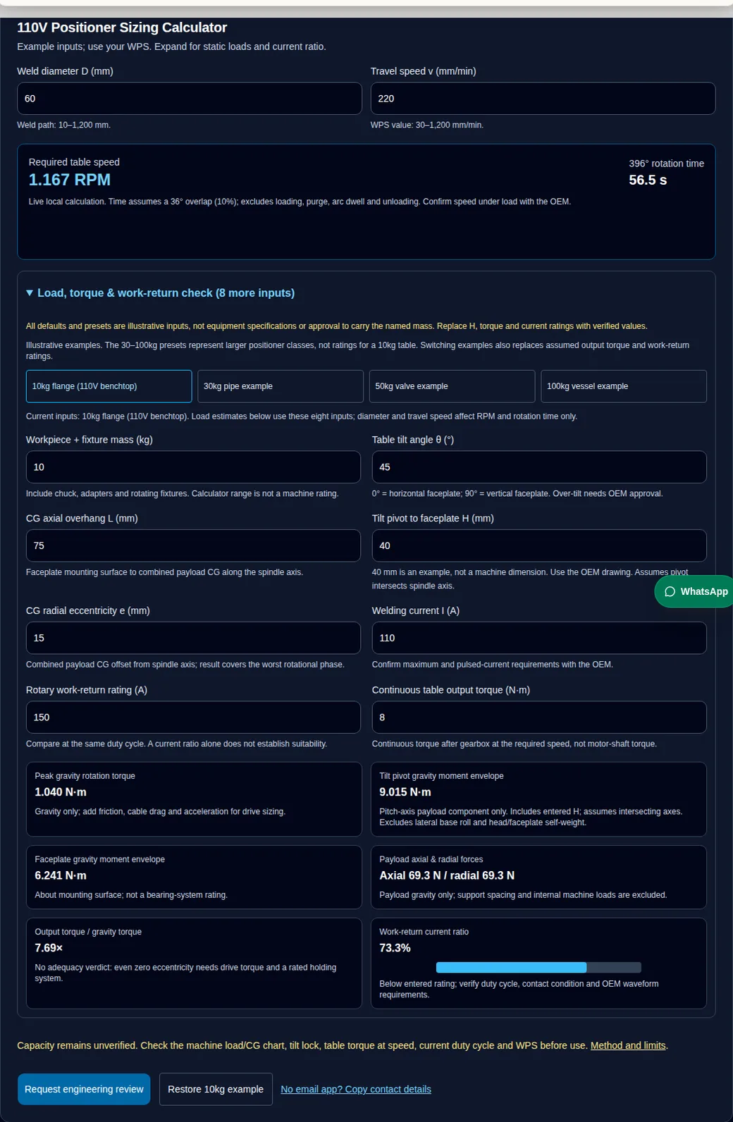
Example inputs; use your WPS. Expand for static loads and current ratio.
Weld path: 10–1,200 mm.
WPS value: 30–1,200 mm/min.
Load, torque & work-return check (8 more inputs)
All defaults and presets are illustrative inputs, not equipment specifications or approval to carry the named mass. Replace H, torque and current ratings with verified values.
Current inputs: 10kg flange (110V benchtop). Load estimates below use these eight inputs; diameter and travel speed affect RPM and rotation time only.
Include chuck, adapters and rotating fixtures. Calculator range is not a machine rating.
0° = horizontal faceplate; 90° = vertical faceplate. Over-tilt needs OEM approval.
Faceplate mounting surface to combined payload CG along the spindle axis.
40 mm is an example, not a machine dimension. Use the OEM drawing. Assumes pivot intersects spindle axis.
Combined payload CG offset from spindle axis; result covers the worst rotational phase.
Confirm maximum and pulsed-current requirements with the OEM.
Compare at the same duty cycle. A current ratio alone does not establish suitability.
Continuous torque after gearbox at the required speed, not motor-shaft torque.
Capacity remains unverified. Check the machine load/CG chart, tilt lock, table torque at speed, current duty cycle and WPS before use. Method and limits.
Published . Reviewed by ServoRotary. Catalogue values and ratings are model-specific; worked examples and sizing calculations represent physics models, not guarantee of specific part compliance.
1. Decisions to make before choosing a 110V positioner
Calculate speed first
Use the WPS travel speed and weld-path diameter. The tool calculates kinematics; it does not select electrical power or certify a machine.
Verify load and geometry together
Mass alone is insufficient. KOIKE publishes separate horizontal/vertical and CG limits. Apply only the exact model chart. KOIKE LD-R series — scope
Confirm power and controls
Check the nameplate and OEM pedal schematic. A 110V label does not establish pinout, arc synchronization or HF TIG compatibility. KOIKE LD-R series — scope
Provide an adequate return path and retain PE
Use the documented work-return connection and required protective bonding. A current ratio is not a duty rating. OSHA 1910.254 — scope
2. Sizing calculation method, vector geometry and physical boundaries
The interactive calculator above produces reproducible static gravity equilibrium estimates for a rigid combined workpiece and fixture assembly. In the kinematic model:
- θ (Tilt Angle): 0° represents a completely horizontal faceplate; 90° represents a vertical faceplate with horizontal rotation axis; 135° represents over-tilt.
- L (Axial Overhang): Distance in mm from the faceplate mounting surface to the combined center of mass (CG).
- H (Pivot Distance): Distance in mm from the tilt trunnion axis to the faceplate surface. Use the OEM drawing; the calculator assumes the pivot intersects the spindle axis.
- e (Radial Eccentricity): Radial offset in mm from the spindle rotation centerline to the combined center of mass.
Note: Friction, acceleration torque, cable drag, and gearbox dynamic efficiencies are excluded from the static gravity estimate and must be evaluated for dynamic motion.
| Output parameter | SI Mathematical equation | Physical interpretation & engineering application |
|---|---|---|
| Rotational speed (n) | n = v / (π · D) | RPM needed to achieve linear travel speed v (mm/min) along weld path diameter D (mm). |
| 396° rotation cycle time (t) | t = 66 / n | Seconds for a 360° revolution plus an illustrative 36° overlap at constant RPM. Actual overlap and sequence come from the WPS. |
| Peak gravity unbalance torque (T_rot) | T = m · g · (e / 1000) · |sin θ| | Cyclical motor torque needed to lift the eccentric load over the top dead-center during rotation. |
| Tilt pivot overturning moment (M_tilt) | M = m · g · [((L + H) / 1000) · |sin θ| + (e / 1000) · |cos θ|] | Payload moment about the tilt pitch axis, not a 3D base overturning resultant. Excludes lateral roll moment, head self-weight and nonintersecting pivot geometry. |
| Faceplate moment envelope (M_face) | M_face = m · g · [(L / 1000) · |sin θ| + (e / 1000) · |cos θ|] | Overturning bending moment referred strictly to the spindle faceplate mounting plane. |
| Axial thrust force (|F_a|) | |F_a| = m · g · |cos θ| | Axial payload gravity resultant; reverses from compression to tension above 90°. Individual bearing reactions are not calculated. |
| Radial shear force (|F_r|) | |F_r| = m · g · |sin θ| | Radial payload gravity resultant. Bearing span, moment-induced reactions and internal machine loads are not calculated. |
| Work-return current ratio (not duty cycle) | Ratio = (I_weld / I_rated) · 100% | Entered welding current divided by entered return rating. Does not establish thermal or pulsed-current suitability. |
Have a drawing and datasheet ready? Request a configuration review with your actual inputs before selecting equipment.
3. OEM evidence and fixture mass: known versus unconfirmed
Manufacturer data illustrate why voltage and a nominal mass label cannot select a positioner. The original KOIKE LD-R table differs from generic marketplace listings. These are catalogue examples, not recommendations for a 10 kg application. KOIKE LD-R series — scope
| Model | Horizontal / vertical maximum load | Speed | What remains to verify |
|---|---|---|---|
| LD-60R | 60 / 30 kg | 0.15–20 RPM | Model load/CG envelope, power option, return duty and accessories |
| LD-150R | 150 / 120 kg | 0.1–6.2 RPM | Same model-specific checks; do not transfer limits to another machine |
| Generic 10 kg / BY / HD listing | Unconfirmed for the exact supplier model | Unconfirmed | Obtain an original dated datasheet and manual; no published rating assumed here |
| ServoRotary application proposal | To be specified after review | To be specified | No catalogue load rating is established by this guide |
Weigh the fixture and workpiece together. The following subtraction is an illustration with an assumed gross mass ceiling, not an OEM derating curve. Allowable overhang and tilt capacity remain unknown until the chart and combined CG are checked.
| Assumed rotating fixture mass | Mass left for workpiece | Unresolved limit |
|---|---|---|
| 0 kg | 10 kg | All mechanical and geometry limits still require confirmation |
| 2.2 kg | 7.8 kg | Chuck dimensions, retention, overhang and tilt |
| 4.0 kg | 6.0 kg | A 40% fixture fraction does not prove remaining capacity |
| 6.3 kg | 3.7 kg | No vertical payload or overhang allowance inferred |
4. 110V supply compatibility and voltage drop
Check permitted voltage and frequency, nameplate input current, grounding and the installation manual. Motor output watts are not the same as mains input VA. The calculator does not size a branch circuit or recommend a cord gauge. A qualified installer should assess the welder and positioner together. OSHA 1910.254 — scope
For an assumed resistive path, ΔV = I × R_loop. The arithmetic below uses a nominal 120 V source and an assumed 20 A event. It is not a permitted cord loading or measured positioner performance. Real impedance, upstream wiring, temperature, controller regulation and event duration matter.
| Assumed R_loop (Ω) | Assumed current (A) | Calculated ΔV (V) | Calculated terminal voltage (V) |
|---|---|---|---|
| 0.10 | 20 | 2.0 | 118.0 |
| 0.25 | 20 | 5.0 | 115.0 |
| 0.40 | 20 | 8.0 | 112.0 |
Do not translate a voltage percentage directly into a speed dip. Record actual supply and loaded speed during commissioning using appropriate equipment and qualified personnel. A regulated supply can still reach its input, output or hold-up limit; use only manufacturer-approved changes.
5. Speed stability and heat input: units and limits
With travel speed v in mm/min, voltage U in V and current I in A, arc energy is 60 × U × I / (1000 × v) kJ/mm. Heat input HI = η × arc energy. The factor 60 converts minutes to seconds. TWI distinguishes arc energy and efficiency-adjusted heat input. TWI — scope
For a constant-power illustration with U = 11 V, I = 65 A and assumed η = 0.6, the baseline at 180 mm/min is 0.143 kJ/mm. These are explanatory inputs, not WPS recommendations or predictions of defects.
| Travel speed (mm/min) | Speed change | Heat input (kJ/mm) | Energy change |
|---|---|---|---|
| 144 | −20% | 0.179 | +25% |
| 180 | Baseline | 0.143 | Baseline |
| 216 | +20% | 0.119 | −16.7% |
Use the applicable WPS and inspection requirements to set process tolerances. Drive type alone does not establish loaded speed uniformity. For pulsed processes, simple average voltage multiplied by average current may not represent time-averaged power.
6. Work return and protective earth: separate functions
Keep required protective earth connected. PE provides protective bonding; the welder work lead completes the welding circuit. Follow the exact machine drawing for its rated work-return terminal or current collector. Do not use the mains PE conductor as the intended welding return or route welding current through bearings.
OSHA 1910.254(c)(2)(iv) addresses adequate bonding or current collection where a fixture is used as a return; (c)(2)(v) addresses connection adequacy. This does not impose universal electrical isolation between every fixture and earth. No universal “PE <15 A” or “bearing voltage <0.30 V” criterion is established here. OSHA 1910.254 — scope
| Function | Connection / assessment | Unresolved without documentation |
|---|---|---|
| Protective earth | Required machine protective bonding stays intact | Conductor and protection requirements for the installation |
| Welding work return | Use a rated OEM-designated connection or approved current collector | Current, waveform, duty, contact and temperature limits |
| Rotary contact condition | Inspect with equipment isolated and per OEM instructions | Maintenance interval, contact force and test criteria |
Contact heating follows P = I²R. An assumed 100 A through 0.001 Ω produces 10 W; through 0.010 Ω it produces 100 W. Neither resistance is asserted to be normal or safe. Dissipation depends on the actual assembly; no cooling or preload recommendation follows from this calculation.
7. Foot controls and arc synchronization
A connector shell, GX16 designation or pin count does not identify a safe electrical interface. Obtain the exact pinout, signal voltage, isolation and approved pedal from the controller manufacturer. Do not trial-wire an unknown pedal or connect a welder trigger to an undocumented input.
| Control mode | Typical intent | Confirm before integration |
|---|---|---|
| Momentary run | Rotate while held, stop on release | Actual release, stop and restart behavior |
| Latching run | A command can leave rotation running after release | Clearly indicated mode and independent stopping arrangement |
| Variable speed pedal | Pedal travel changes speed reference | Compatible sensor/interface and repeatable WPS travel speed |
| Arc synchronization | Coordinate gas, arc and rotation where supported | Compatible documented interlocks, timing and fault/stop sequence |
Momentary and latching modes have different stopping behavior. A foot switch is not automatically an emergency stop. Arc dwell, overlap and gas timing must follow the applicable procedure and controller manual; this guide provides no universal delay values.
8. HF TIG compatibility and commissioning
HF arc starting can disturb nearby electronics. Request the positioner manufacturer’s evidence for TIG compatibility, installation arrangement and documented EMC scope. KOIKE describes noise-resistant design on its LD-R page; that claim does not certify other positioners. KOIKE LD-R series — scope
Follow approved cable routing, shielding and bonding instructions. Do not retrofit mains TVS devices, change protective bonding or assume a component isolation rating makes an assembled controller suitable. If controls reset or motion becomes unexpected, stop use and have the system assessed.
Commission with the exact power source and installed controls under a supervised plan, checking start, stop and restart behavior. Confirm the installation before exposing a loaded machine or personnel to a welding trial.
9. Hollow spindle and purge requirements
A through-bore provides space for a purge arrangement; it does not by itself prevent a hose from winding. Continuous rotation may require a compatible rotary union. Specify bore clearance, seals, gas compatibility and fixture routing with the supplier.
Linde explains that purge gas, containment and flow must suit the material and joint. Establish oxygen limits, flow, venting and acceptance in the qualified procedure. No fixed four-volume purge or universal stainless/titanium ppm limit is justified here. Linde — scope
As an idealized perfect-mixing model only, C/C₀ = exp(−N), where N = flow × time / volume for zero-oxygen inlet gas. Four exchanges leave about 1.83% of the initial concentration: starting from 20.9% oxygen, approximately 3,828 ppm remain. This demonstrates why a volume-count shortcut cannot certify low oxygen. Real leakage, dead spaces and mixing differ; verify the specified endpoint with the required procedure and measurement.
10. Drive tradeoffs and procurement cost
| Architecture | Potential benefit | Tradeoff / evidence to request |
|---|---|---|
| DC motor with gearbox | Simple speed control and compact package | Verify low-speed behavior under actual load; worm gearing is not automatically a rated holding brake |
| Stepper with microstepping | Repeatable commanded motion | Check resonance, missed steps, feedback and load-speed envelope |
| Encoder-controlled servo | Feedback can regulate loaded motion | Tuning, cost and integration; encoder presence alone proves no ripple limit |
| Existing fixture with manual rotation | Low initial integration effort | Assess repeatability, operator access and whether the WPS can be met |
Compare total installed cost: approved chuck and adapter, load support, rated return, controls, guarding, supply work, purge hardware, shipping and commissioning. No verified price or payback is available here. Request itemized quotes for the same configuration. Upgrade only when measured performance or integration requirements justify it.
11. Worked scenarios: calculations and unresolved decisions
These are hypothetical screening examples, not approved welding procedures or equipment selections. H is assumed 40 mm in all cases. The quoted 150 A return rating is an illustrative input with unverified duty; no scenario is approved for welding by these numbers. These differ from the named calculator presets. To reproduce a row, restore the 10kg example, keep H = 40 mm, set the work-return rating to 150 A and replace every input listed in that row. Keep the illustrative 8 N·m torque input only to populate the worksheet; this table does not assess torque reserve.
| Scenario | Inputs (kg, °, mm, mm/min, A) | Calculated output | Next decision |
|---|---|---|---|
| Small flange | m=8; θ=90; L=65; e=10; D=50; v=180; I=110 | 1.146 RPM; 57.6 s; T_rot=0.785 N·m; M_tilt=8.238 N·m; current ratio 73.3% | Load/CG chart and return duty unknown: request exact OEM review |
| Balanced tube | m=5.2; θ=45; L=80; e=0; D=38.1; v=200; I=65 | 1.671 RPM; 39.5 s; T_rot=0; M_tilt=4.327 N·m; current ratio 43.3% | Zero gravity drive torque is not zero drive demand; verify holding and purge arrangement |
| Larger MIG assembly | m=32; θ=0; L=140; e=25; D=114; v=320; I=185 | 0.894 RPM; 73.9 s; T_rot=0; M_tilt=7.845 N·m; current ratio 123.3% | Exceeds entered 150 A rating; select a suitable documented return system and an appropriate load class |
| Long overhang | m=4.5; θ=90; L=220; e=15; D=76; v=160; I=55 | 0.670 RPM; 98.5 s; T_rot=0.662 N·m; M_tilt=11.474 N·m; current ratio 36.7% | Confirm cantilever, tilt retention and bearing limits; low current does not resolve mechanical risk |
12. Misuse, cost and application mismatch risks
| Risk | Consequence | Mitigation / alternative |
|---|---|---|
| Ignoring fixture mass or CG | Load or retention limits can be exceeded | Weigh the assembly and request a load/CG review; use a larger rated class or support arrangement if needed |
| Treating PE as the work-return lead | Unintended current paths, heating or equipment damage | Keep required PE; use OEM return connection and qualified installation checks |
| Assuming an unknown pedal pinout | Electrical damage or unexpected motion | Obtain an approved pedal and exact controller schematic |
| Buying by voltage or unloaded speed alone | Required travel speed may be unstable under load | Request a loaded trial at the required RPM and compare approved drive options |
| Omitting integration costs | Budget misses fixtures, safety or commissioning work | Obtain itemized installed-cost quotes for comparable configurations |
| Assuming bore equals purge capability | Hose winding or inadequate root protection | Review gas transfer, containment, endpoint measurement and WPS before selection |
13. Engineering review and commissioning sequence
- Document measured combined mass, CG, H, L, e, intended tilt range and fixture retention.
- Obtain the exact load/CG chart, output torque at required speed, holding limits, return duty and nameplate data. Resolve missing ratings before a loaded trial.
- Have qualified personnel check installation, protective bonding and the intended work-return path against the OEM manual. Do not disconnect PE to impose isolation.
- Use the OEM commissioning plan to check retention, clearance, routing, safe stops and restart behavior before welding. Do not release a lock or cut power under an unsupported load to test holding.
- Complete a controlled trial with the applicable WPS. Check actual speed, required purge endpoint and weld acceptance before production.
14. Frequently asked engineering questions (16 answers)
Categorized reference addressing capacity geometry, 110V utility power, foot control compatibility, HF TIG commissioning, welding process, and purge aerodynamics.
Review our OEM engineering workflow or use the contact and RFQ form if you do not have an email application.
Load and sizing
What does a 10kg welding positioner rating mean?
A nominal label requires a model-specific load/CG chart. Include the chuck, adapters and workpiece, and check every intended tilt angle. The calculator cannot approve a 10 kg assembly for a 10 kg machine.
Does chuck weight reduce the available workpiece mass?
Include all rotating fixturing in the combined load. With an assumed 10 kg gross allowance and 4 kg fixture, subtraction leaves 6 kg as a mass-only ceiling; CG, moment, retention and tilt limits can reduce it further.
Why does a centered pipe still create a tilt moment?
Zero radial eccentricity removes the gravity component of rotation torque. With a tilted spindle, axial overhang still creates a gravity moment about the faceplate and tilt pivot. Friction and acceleration also remain.
Is the same derating factor valid for all 110V tables?
No. Input voltage does not establish load capacity. Use the exact manufacturer chart, permissible CG, pivot geometry and retention requirements.
110V power and return path
Can a 110V rotary welding positioner use any wall outlet?
Check its nameplate voltage range, frequency, input current and manual. A 110V marketing label does not establish 120V compatibility or branch-circuit suitability. Have the installation and any shared welder supply checked for the actual load.
Does this calculator size the 110V electrical supply?
No. It calculates RPM, rotation time, static gravity loads and an entered current ratio. It does not calculate mains input current, electrical protection, EMC immunity or thermal duty.
Should protective earth be disconnected to stop welding interference?
Never remove required protective earth. Provide the welding return connection specified by the manufacturer. Protective bonding and the work-return function are distinct, but this does not require every machine to be electrically isolated between them.
Does a 73% work-return current ratio prove continuous duty?
No. Current waveform, duty cycle, contact condition and thermal limits remain unverified. Compare the same duty conditions in the OEM documentation. A ratio over 100% flags a mismatch with the entered rating.
Foot controls and TIG compatibility
Is there a universal GX16 foot-pedal pinout?
No universal positioner pinout is established here. Connector shape and pin count do not establish voltage or function. Use the exact controller schematic and approved pedal; do not trial-wire an unknown connector.
Are momentary and latching pedals interchangeable?
No. A momentary input commonly runs while held; a latching mode can continue after release. Confirm the actual controller behavior, safe stop and restart prevention before selecting a pedal.
Does an ordinary foot switch synchronize the welding arc?
Only if the controller and welding source support a documented compatible interface. Confirm signal types, sequencing, stop behavior and procedure timing. A rotation pedal alone does not imply arc-start control.
How should HF TIG compatibility be confirmed?
Ask for the manufacturer EMC and TIG compatibility documentation for the exact configuration. Verify stop and control behavior during a controlled commissioning trial. A metal enclosure or a generic isolation component rating alone is insufficient.
Weld process and purchasing
How do I calculate circumferential welding RPM?
Use n = v / (π × D) with v in mm/min and weld-path D in mm. At D = 60 mm and v = 220 mm/min, n is about 1.167 RPM. Use the WPS travel speed and verify loaded output speed.
How does speed affect heat input?
For constant voltage, current and efficiency, heat input is inversely proportional to speed: 20% slower means 25% more energy per length. With v in mm/min, HI = 60 × η × U × I / (1000 × v) in kJ/mm. This does not predict a specific defect or acceptance limit.
Are four purge-volume exchanges enough for every joint?
No. Flow, mixing, leaks, material and the specified oxygen limit matter. A timing estimate cannot replace the qualified purge procedure and measured oxygen where required. A hollow spindle also needs a compatible gas transfer arrangement to prevent hose winding.
What should I send for an equipment review?
Send the combined mass and CG drawing, tilt range, seam diameter, WPS speed and current/duty, power nameplate requirements, chuck details, pedal mode, purge needs and intended production cycle. Request the OEM load/CG chart and a configuration-specific quote.
15. Primary sources, source scopes and evidence boundaries
Primary source scopes checked on . Mathematical equations and kinematic sizing models reflect physics and vector geometry principles; they are not warranties of specific commercial equipment compliance. Fabricators must confirm final ratings on manufacturer equipment datasheets.
KOIKE LD-R series: original manufacturer specifications ↗
Lists model-specific loads, speed, CG and power data. LD-60R is 60 kg horizontal / 30 kg vertical, not a generic 10 kg machine. The manufacturer describes TIG noise resistance. Catalogue limits remain subject to the exact model and configuration.
OSHA 1910.254: arc welding and cutting ↗
US regulation: (c)(2)(i) frame grounding; (c)(2)(iv) adequate current collection for return fixtures; (c)(2)(v) connection adequacy; (d)(3) equipment installation checks. Does not specify a universal PE trip current, spindle-bearing voltage limit or pedal pinout. Other jurisdictions require local rules.
TWI: heat input versus arc energy ↗
Explains energy per unit length and process efficiency. Our speed sensitivity examples assume constant voltage, current and efficiency; they do not establish weld acceptance or a permitted motor speed ripple.
Linde: weld purging with backing and trailing gases ↗
Explains shielding roles and why gas, containment and flow depend on the material and joint. Does not establish a universal oxygen ppm limit or a fixed number of volume changes for every weld.
For multi-axis machining and precision positioning setups, see the tilting rotary table guide or the precision tilting rotary table engineering analysis.
16. Request an engineering application review & RFQ consultation
Need assistance sizing a 110V benchtop welding positioner turntable, selecting chuck fixturing, integrating hollow spindle back-purging, or configuring synchronized foot switch controls? Submit your application parameters for engineering review.