
Tilting Rotary Table: 10-Inch Sizing Calculator
Check 10-inch (254 mm) geometry, payload and cutting moments. Enter your loads, then review fit, ratings and drive limits.
Tilting table moment calculator
Preparing calculator…
Live example, not a table capacity approval.
Published and reviewed by ServoRotary on . Next review: May 2027, or earlier if a cited specification changes. This worksheet documents software calculations, not physical machine testing.
1. Executive Summary: Four Selection Decisions
Start with a payload moment screen, then request evidence for the complete installed assembly. Dimensions, ratings and accuracy are separate selection decisions.
Measure CG from the pivot
Doubling L doubles the height contribution to gravity moment at the same nonzero tilt. This follows from the calculator equation; cutting and eccentricity contributions do not double automatically.
Separate stationary and moving states
Clamps hold indexed cuts; a moving axis requires drive torque and thermal review. Sankyo mechanism explanation describes one design, not every table.
254 mm is a dimension, not a fit guarantee
A catalogued 250 mm model has its own mounting, mass and tilted-load limits. Check its actual drawing. Kitagawa model example.
Translate angular error at your working radius
Assuming 10 arcsec gives 6.16 µm at 127 mm and 14.54 µm at 300 mm. These calculated angular contributions exclude other errors; positioning tests provide a different kind of evidence.
For manufacturing engineers and buyers screening 3+2 or simultaneous 5-axis applications. High-speed mill-turn duty, automated safety functions and final machine acceptance require a model-specific engineering study.
2. Kinematic Architecture: Trunnion vs. Cantilever
A tilt axis rotates the cradle while the rotary axis turns the platen. A dual-support trunnion offers another load path; a cantilever can simplify access and reduce footprint. Neither arrangement alone establishes a stiffness multiplier or payload capacity.
| Design | Potential benefit | Evidence needed |
|---|---|---|
| Dual support | Additional support for an overhung load | Loaded deflection, alignment and thermal expansion provision |
| Cantilever | Open tool access and potentially smaller installation | Bearing load envelope and fixture moment at worst tilt |
| Both | Two-axis positioning | CNC axis options, kinematic model, postprocessor and collision check |
3. 10-Inch Dimensions & Machine Envelope
The phrase “10 tilting rotary table” commonly refers to a 10-inch (254 mm) faceplate. A 250 mm catalog unit is a nearby metric size. Neither designation establishes compatibility with a particular VMC.
| Nominal diameter | Exact conversion (mm) | What remains unknown |
|---|---|---|
| 6 inches | 152.4 | Bore, slots, overall size, swing and load: verify drawing |
| 8 inches | 203.2 | Bore, slots, overall size, swing and load: verify drawing |
| 10 inches | 254.0 | Bore, slots, overall size, swing and load: verify drawing |
| 12 inches | 304.8 | Bore, slots, overall size, swing and load: verify drawing |
| 16 inches | 406.4 | Bore, slots, overall size, swing and load: verify drawing |
Include table self-mass, fixture, part, tooling, cables and hoses in the machine load and swept-volume check. Confirm spindle-to-part reach at both tilt extremes. Request a 3D assembly and simulate the actual program before purchasing.
4. Drive Mechanisms & Evidence to Request
Compare reversal behaviour, compliance and duty rather than assigning a guaranteed accuracy or speed to a mechanism family. Sankyo describes preloaded roller contact; supplier claims still require application limits.
| Drive | Useful property | Tradeoff / evidence needed |
|---|---|---|
| Dual-lead worm | Axial adjustment can change backlash | Friction, heat, wear history; use model-specific service instructions |
| Roller cam | Preloaded rolling contact can reduce reversal clearance | Load limits, torsional compliance and lubrication remain relevant |
| Direct drive | No transmission gear backlash | Complete torque-speed/duty study, encoder and controller performance, cooling provision |
5. Clamping, Supply Conditions & Power-Loss Behaviour
A positioning clamp rating describes holding under specified conditions. It is not an emergency-stop certification. Spring-applied designs can retain holding force without release pressure, but engagement delay and motion during stopping depend on the complete system; zero droop is not guaranteed.
| Actuation | Known principle | Must be confirmed |
|---|---|---|
| Pressure applied | Air or oil creates clamp force | Pressure, friction interfaces, axis-specific torque and loss-of-supply state |
| Air-over-oil booster | Air pressure drives hydraulic pressure locally | Booster ratio, actual output pressure, cycle time and circuit |
| Spring applied / pressure released | Spring force applies holding; pressure releases | Holding vs dynamic stopping rating, response time, wear, interlocks and allowable droop |
As a model-specific example, the TT251/TW251 catalog lists rotary/tilt clamp torque separately: 900/1,200 N·m at the stated pneumatic 0.45 MPa / hydraulic 3.5 MPa conditions. Its faceplate is 250 mm, not 254 mm. Do not transfer either axis rating to another table or a different supply circuit.
6. Cutting Force & Moment Method
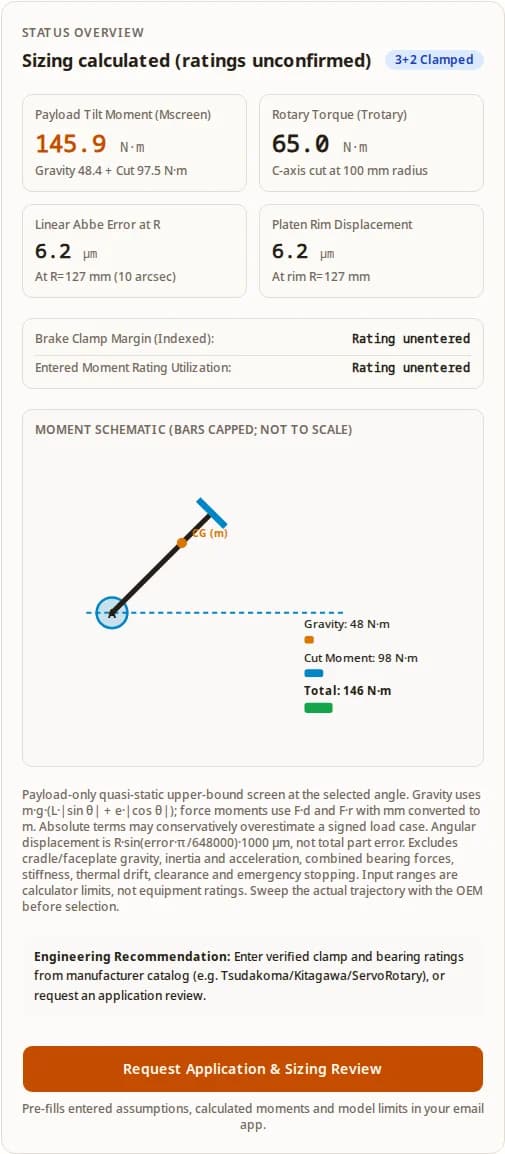
The vector moment about a chosen pivot is r × F; project it onto that axis to obtain signed torque. F·d is a scalar upper bound when d is a perpendicular arm or a conservative distance bound. The same resultant force is used for the independent rotary screen F·r; these screens need not represent simultaneous maxima.
Convert millimetres to metres for moment calculations. L is CG height along the platen normal from the tilt pivot; e is the magnitude of an in-plane offset. The absolute sum is an envelope, not the signed net load. Evaluate all actual tilt angles; the maximum need not occur at 90°. The tool omits cradle gravity, inertia/acceleration and complete force interaction.
7. Bearings & Complete Assembly Load Limits
A bearing moment percentage is a scalar comparison only. The entered allowable moment must correspond to the complete assembly, axis, clamping state and duty, not a raw bearing catalog maximum.
| Load or property | Why it matters | Next evidence |
|---|---|---|
| Axial / radial force | Combined force-moment interaction changes allowable loading | OEM assembly load diagram at the actual CG |
| Cradle and faceplate gravity | Not included in payload inputs | Complete moving-mass and CG model |
| Acceleration / inertia | Drive torque and stopping loads vary with the trajectory | Motion profile and drive simulation |
| Stiffness and fatigue | A load below rating can still cause part error or wear | Loaded deflection and duty/life assessment |
8. Spatial Abbe Error & Linear Displacement Stackup
In multi-axis tilting tables, an angular positioning error θerr on the tilt axis does not remain an abstract angle: it magnifies linearly with distance R from the pivot centerline. This angular contribution is one part of a full error budget; it does not establish total part tolerance.
The Abbe Lever Arm Equation
Linear displacement δ at distance R is calculated as:
For example, when milling a deep pocket at a distance R = 200 mm from the tilt pivot, an angular backlash or thermal drift of just 15 arc-seconds translates to a linear tool center offset of 14.5 µm.
| Angular Error (arcsec) | At R = 50 mm | At R = 100 mm | At R = 127 mm (10" rim) | At R = 200 mm | At R = 300 mm |
|---|---|---|---|---|---|
| 2 arcsec (assumed) | 0.48 µm | 0.97 µm | 1.23 µm | 1.94 µm | 2.91 µm |
| 5 arcsec (assumed) | 1.21 µm | 2.42 µm | 3.08 µm | 4.85 µm | 7.27 µm |
| 10 arcsec (assumed) | 2.42 µm | 4.85 µm | 6.16 µm | 9.70 µm | 14.54 µm |
| 15 arcsec (assumed) | 3.64 µm | 7.27 µm | 9.23 µm | 14.54 µm | 21.82 µm |
| 30 arcsec (assumed) | 7.27 µm | 14.54 µm | 18.47 µm | 29.09 µm | 43.63 µm |
9. Metrology: Match Each Question to Its Test
ISO 230-2 concerns individual-axis positioning; ISO 230-7 concerns rotary error motion; ISO 10791-6 concerns kinematic performance including coordinated axis movements. Their public summaries support these scopes, not the numerical tolerance classes formerly attributed to them.
Renishaw AxiSet checks rotary pivot errors using machine-specific macros and a reference sphere. Confirm supported controller options before promising parameter correction. Agree instruments, uncertainty, temperature, feed, load, travel and acceptance limits with the builder.
10. Thermal Drift & Production Duty
Friction and motor losses can shift a rotary pivot as the assembly heats. No universal temperature rise, drift magnitude, coolant flow or warm-up time can be assigned to every 10-inch table. Obtain model-specific utility requirements and record cold, warm and production-duty measurements.
For a moving tilt axis, compare the actual trajectory with the drive thermal model, continuous and peak torque curves, cooling conditions and duty cycle. If that evidence is unavailable, keep the selection provisional and consider indexed machining for operations compatible with a stationary clamp.
Request a drive and duty review11. Maintenance & Ownership Cost
Backlash adjustment is model-specific. Secure the assembly and follow the builder service procedure; this page does not specify a test torque, adjustment direction, graduation size or residual clearance. An incorrect adjustment can bind the drive as it warms.
- Record bidirectional positioning and backlash before service under repeatable conditions.
- Identify the exact drive revision and obtain its adjustment and lubrication instructions.
- Have qualified service staff perform the specified procedure with the assembly secured.
- Recheck the permitted travel, drive current, temperature and positioning against the OEM limits.
| Cost item | Include in every proposal | Known / unknown |
|---|---|---|
| Purchase and integration | Table, drive, CNC options, postprocessor and commissioning | Unknown until written quotation |
| Fixtures and utilities | Adapter, workholding, air/oil supply, cooling and rotary unions | Configuration-specific |
| Scheduled service | Oil/grease, seals, inspection and qualified labour | Use OEM intervals; no universal hours |
| Downtime and acceptance | Service access, spare parts and repeat acceptance checks | Use your shift pattern and service agreement |
12. Inertia & Balancing: Derived Examples, Not Limits
For a rigid ideal reduction with speed ratio i = motor speed / load speed, reflected load inertia is JL/i². Include transmission inertia, efficiency, friction and structural compliance separately. There is no universal JL/JM limit or servo bandwidth established here. A gearbox reduces reflected inertia; it does not remove fixture bending, unbalance or gravity moment.
Derived centrifugal example: m = 5 kg, r = 0.05 m gives 9.87 N at 60 rpm and 246.74 N at 300 rpm. No special onset speed is implied; force grows with speed squared.
Illustrative balance calculation only: if the builder selects G = 2.5 mm/s for a rigid 20 kg assembly at 100 rpm, ω = 10.472 rad/s, eper = 0.2387 mm and Uper = 4,775 g·mm. At G = 6.3 and 30 rpm for the same mass, Uper = 40,107 g·mm. Grade choice, correction planes and suitability require agreement with the builder. ISO 21940-11:2016 replaces ISO 1940-1:2003 for rigid-rotor balancing; a grade alone is not a cutting-load approval.
13. Five Reproducible Sizing Scenarios
Hypothetical calculations, not measured machining results or customer case studies. Units in the input column are kg; degrees; mm; mm; N; mm. Each uses the unsigned payload equation above and excludes cradle/acceleration loads. No model is selected by this table.
| Scenario | m; θ; L; e; F; d | Mg (N·m) | Mc (N·m) | Total (N·m) | Next action |
|---|---|---|---|---|---|
| 10-inch reference | 45; 45; 130; 25; 650; 150 | 48.37 | 97.50 | 145.87 | Start with the worked example; confirm tilted payload and complete assembly ratings. |
| Heavy indexed fixture | 85; 30; 160; 30; 1400; 180 | 88.34 | 252.00 | 340.34 | Review fixture CG, cutting load and clamp requirements before choosing a model. |
| Continuous impeller concept | 28; 75; 100; 15; 400; 120 | 27.59 | 48.00 | 75.59 | Request motor/thermal sizing; a clamp rating cannot approve moving-axis duty. |
| Compact aluminum fixture | 18; 60; 75; 10; 320; 95 | 12.35 | 30.40 | 42.75 | Check mounting and clearance even if the scalar moment is small. |
| Tall fixture concept | 65; 60; 280; 30; 1200; 250 | 164.13 | 300.00 | 464.13 | Reduce overhang where possible; check stiffness, swing and trajectory loads. |
14. Evidence, Unknowns & Decision Risks
| Source | What it can establish | What remains to agree |
|---|---|---|
| ISO 10791-6:2014 — Speeds and interpolations | Kinematic tests of coordinated NC linear/rotary movements. Public abstract verified; exact test setup and acceptance contract require the applicable full text. | Applicable configuration, conditions and acceptance limits |
| ISO 230-2:2014 — Axis positioning accuracy and repeatability | Measurement and evaluation of positioning for individual linear and rotary NC axes; not a universal tolerance class for 10-inch tables. | Applicable configuration, conditions and acceptance limits |
| ISO 230-7:2015 — Geometric accuracy of axes of rotation | Rotary error motion and speed-induced axis shifts; surface runout and angular positioning are separate quantities. | Applicable configuration, conditions and acceptance limits |
| ISO 21940-11:2016 — Balancing of rigid rotors | Procedures and tolerances for rigid-behaviour rotors; replaces ISO 1940-1:2003. No balance grade is assigned here to every tilting table. | Applicable configuration, conditions and acceptance limits |
| Risk | Consequence | Action / alternative |
|---|---|---|
| Misuse: payload screen treated as approval | Omitted self-weight, shock or stopping loads can dominate | Obtain complete assembly and emergency-stop evidence from the builder |
| Cost: integration omitted from price | CNC options, utilities and fixtures increase delivered cost | Compare itemized installed quotes and a sample-part acceptance plan |
| Scenario mismatch: indexed rating used in motion | Clamp torque cannot carry a moving axis | Size the drive for the trajectory; use indexed cuts where the part allows |
| Evidence gap: catalog or standard name treated as measured result | Unproven accuracy or fit | Request dated drawings, test report and installation conditions |
Public catalog values apply only to their named model. Numerical examples on this page are derived assumptions, not measured vendor comparisons. Supply pressure, load orientation, speed and controller configuration must accompany every purchasing decision.
15. Frequently Asked Technical Questions (FAQs)
Below are categorized answers to the 24 most common engineering and integration questions regarding tilting rotary tables, 10-inch dimensions and model-specific envelopes, clamping systems, metrology, and dynamic control.
10-Inch Geometry & Integration
What does "10 tilting rotary table" mean?
It commonly means a 10-inch faceplate: exactly 254 mm. Treat a 250 mm catalog table as a nearby size, not an interchangeable mounting drawing. Confirm the actual diameter, bore, slots and swing envelope.
Will a 10-inch table fit any 40-taper VMC?
No. Check the entire unit and fixture against machine travel, spindle nose clearance, enclosure, machine table load and the swept volume at every commanded tilt angle. Taper size alone does not establish fit.
Does a tilting table make any 3-axis machine simultaneous 5-axis?
Only with compatible axis drives, CNC options, interpolation, kinematic compensation, postprocessor and collision verification. An independent indexer may support only positional 3+2 operation.
Is faceplate diameter a payload rating?
No. Obtain separate horizontal/tilted payload and moment limits, permissible work inertia and clamped/unclamped conditions for the chosen model. A diameter cannot determine bearing life or holding torque.
Can I reuse a 250 mm fixture on a 254 mm faceplate?
Only after checking the drawing, register, fasteners, support area and swept clearance. The 4 mm difference in diameter is not the only interface difference.
Which mass belongs in the calculator?
Enter the combined workpiece and fixture mass and their combined center of gravity. The tool excludes cradle/faceplate gravity; the OEM must include the complete moving assembly in final sizing.
Loads & Calculator Boundaries
How is the gravity moment calculated?
The payload envelope is Mg = m·9.80665·(L·|sin θ| + e·|cos θ|), with L and e in metres. It is an unsigned conservative screen at one selected angle, not a signed trajectory simulation.
Where do I measure CG height L?
Measure along the platen normal from the tilt pivot to the combined payload CG. Measuring only from the faceplate omits the pivot-to-face offset and can understate moment.
What does F times d represent?
F is the resultant force magnitude in newtons and d its perpendicular arm about the tilt axis in metres. F·d is a scalar upper-bound screen; a known vector model uses the tilt-axis projection of r × F.
Is the 2× clamp target an industry safety standard?
No. It is an illustrative screening target used on this page. The OEM must choose the required margin, shock factors and load combinations for the actual duty. A ratio above 2× is not approval.
Why can a zero-load case show no clamp ratio?
Dividing a clamp rating by zero modeled moment is undefined. The tool shows N/A, not infinite margin. The physical assembly still has self-weight, inertia and other omitted loads.
What centrifugal force comes from a 5 kg eccentric mass at 50 mm?
Using Fc = m·r·(2πn/60)² gives 9.87 N at 60 rpm and 246.74 N at 300 rpm. These are derived examples with r = 0.05 m, not machine ratings or a speed approval.
Drives, Clamps & Operating Risk
Can the clamp carry torque while its axis is moving?
A positioning clamp must be released during that axis movement. The drive must meet the complete trajectory load, including gravity, cutting, acceleration and losses, within its thermal duty.
Is a spring-applied brake guaranteed to prevent all droop?
No. Response time, stopping capability, wear, torque reserve, valves and the machine control sequence must be verified. A static holding rating does not certify emergency stopping or zero movement.
Does loss of air always release the table?
It depends on the actual circuit and clamp design. Review spring action, pressure storage, valves and interlocks with the builder; do not infer the power-loss state from the supply type.
Is hydraulic clamping always stronger than pneumatic?
No. Torque also depends on friction interfaces, piston geometry and pressure. Compare the chosen model and axis at its specified supply conditions, rather than assigning a universal torque by actuator type.
Does zero backlash mean zero compliance or wear?
No. It describes reversal clearance. Bearings, structure, transmission and servo response still affect deflection and accuracy. Check loaded performance and maintenance requirements.
What is the universal direct-drive inertia ratio limit?
There is none established by this page. For reduction i, reflected load inertia is JL/i²; acceptance also depends on the motor, drive, structural modes, tuning and trajectory. Ask for supplier simulation and testing.
Metrology, Maintenance & Decision Evidence
How does angular error translate into linear displacement?
With R in mm and error in arcseconds, δ = R·sin(error·π/648000)·1000 µm. An assumed 10 arcsec at R = 127 mm gives 6.16 µm. This is one angular contribution, not total part tolerance.
What does ISO 230-2 assess?
It specifies methods to determine positioning accuracy and repeatability of individual NC axes. Request measured bidirectional results for the installed machine and the agreed conditions.
What does ISO 10791-6 assess?
It covers kinematic tests including coordinated movements of linear and rotary axes. It does not make the calculator a test certificate or establish a universal 10-inch performance class.
Is surface runout the same as rotary axis error motion?
No. Surface form, centering and axis error motion can contribute differently. ISO 230-7 addresses geometric axis error motion; a single dial-indicator runout number does not isolate every cause.
How often should a worm drive be adjusted?
Use the selected model maintenance manual and measured backlash history. No universal adjustment interval, rotation direction, torque or graduation value is supplied here.
Which balance grade and ownership cost should I specify?
Agree balance requirements with the builder using the actual speed and assembly, referencing ISO 21940-11 where applicable. Compare written quotes including CNC integration, fixtures, utilities, service and downtime; universal cost multipliers are unsupported.
16. Verifiable Standards & Technical References
Sources checked on 1 November 2026. Manufacturer evidence is model-specific; ISO scope statements use public abstracts. Numerical examples are derived, and missing model limits remain unconfirmed:
- Kitagawa TT251/TW251 and TT321/TW321 catalog
Model-specific example: 250/320 mm faceplates, separate rotary/tilt clamp ratings and horizontal/tilted payload limits. Confirm configuration and pressure on the current order drawing.
- Sankyo RollerDrive CNC technology
Manufacturer explanation of preloaded roller contact. Zero-backlash terminology does not establish an allowable cutting load or emergency-stop rating.
- ISO 10791-6:2014 — Speeds and interpolations
Kinematic tests of coordinated NC linear/rotary movements. Public abstract verified; exact test setup and acceptance contract require the applicable full text.
- ISO 230-2:2014 — Axis positioning accuracy and repeatability
Measurement and evaluation of positioning for individual linear and rotary NC axes; not a universal tolerance class for 10-inch tables.
- ISO 230-7:2015 — Geometric accuracy of axes of rotation
Rotary error motion and speed-induced axis shifts; surface runout and angular positioning are separate quantities.
- ISO 21940-11:2016 — Balancing of rigid rotors
Procedures and tolerances for rigid-behaviour rotors; replaces ISO 1940-1:2003. No balance grade is assigned here to every tilting table.
- Renishaw AxiSet Check-Up
Machine-specific probing macros and reference sphere for checking rotary pivot-point errors; parameter correction depends on controller support.
17. Request an Engineering Application Review
Verify Your 10-Inch or Custom Tilting Rotary Table Installation
Send your machine and controller model, CAD envelope, fixture and part mass, CG location, cutting forces and motion profile. Request compatible drawings, axis ratings and an acceptance plan before selecting a drive or clamp.