
1. Normalize the angle
The unit selector converts arc-seconds, arc-minutes, or degrees to one internal arc-second value for this run.
Engineers and buyers can convert the target angle to workpiece displacement, then screen encoder, backlash, and thermal inputs against it.
Convert the angle to workpiece displacement. Optional checks flag entered values above it; they do not predict installed-axis accuracy.
Method limit: values are checked one at a time, not combined into an uncertainty budget. Verify installed positioning under stated conditions.
The unit selector converts arc-seconds, arc-minutes, or degrees to one internal arc-second value for this run.
The entered workpiece radius turns the target angle into an estimated tangential displacement at that point.
Encoder bits give a nominal count interval under the stated 2^N counts-per-revolution assumption.
Backlash and thermal entries are checked independently; the tool does not combine them into an uncertainty budget.
A screening result is not an installed-axis test. Use it to identify data needed from the supplier or test report.
Normalize the angle, project it at the radius, then compare optional inputs one at a time.
A screening result depends on the inputs and stated model limits.
One arc-second is an angular increment of 1/3,600 of a degree (about 4.848 microradians). At a radius of 100 mm, that angle corresponds to about 0.485 µm of tangential movement; the linear amount scales with radius.
θ = π / 648,000 rad
s ≈ r × θ for a small angle
This converts an angular command into a geometric distance. It does not claim that an encoder, table, or installed axis can position to that increment.
For a measuring instrument, resolution has a specific metrology definition: the smallest change that produces a perceptible indication, as defined in BIPM VIM 4.14. This page screens a target angle; it does not establish the resolution or accuracy of a specific machine.
NIST SP 330, Section 5: plane angle and radiansFor a unit-only conversion, use the arc-second to degree converter.
This reproducible software example uses a 1 arc-second target, a 100 mm workpoint radius, and a nominal 23-bit single-turn encoder. It illustrates the calculation only; no machine was measured.
| Quantity | Calculation | Result |
|---|---|---|
| Angle in radians | π ÷ 648,000 | 4.8481368 × 10⁻⁶ rad |
| Arc-length projection | 100 mm × angle × 1,000 µm/mm | 0.4848 µm |
| Nominal encoder count interval | 1,296,000 arcsec ÷ 2²³ counts | 0.1545 arcsec/count |
The encoder count interval describes nominal command/readout granularity only. It does not establish installed-axis accuracy, repeatability, or uncertainty.
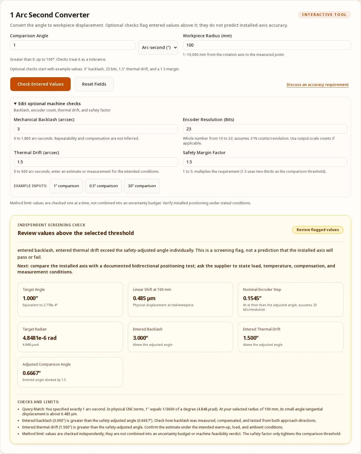
The result is a deterministic comparison based on the values entered in the form. It helps organize a preliminary review; it does not simulate a complete machine or verify a supplier specification.
The unit selector normalizes arc-seconds, arc-minutes, or degrees to arc-seconds before calculating.
The entered radius projects the target angle to a small-angle tangential estimate at that workpoint.
The nominal count interval assumes 2^N equally spaced counts per revolution. Interpolation, noise, installation, and control response are not modeled.
Backlash and thermal entries are compared independently. The margin factor changes the screening threshold; it is not a standards requirement, measured uncertainty, or acceptance result.
If the value affects a part decision, request bidirectional output-table measurements under the intended load, temperature, and approach direction. Use the guide below for the unit definition and accuracy terminology.
Read the arc-second definition and conversion guide for the exact unit relationships.
These are mechanism-level trade-offs described by the cited manufacturers, not guaranteed performance ranges for every product. Compare the same test metric, load, temperature, approach direction, and measurement method before selecting a rotary axis.
| Drive | What the mechanism can offer | What to verify for a 1″ target |
|---|---|---|
| Direct drive | No reduction mechanism between motor and table; one manufacturer describes this as avoiding drive backlash and supporting high-speed indexing. TSUDAKOMA mechanism notes. | Output-side positioning error and repeatability under load, thermal behavior, servo settling, and the encoder location. |
| Roller cam | Sankyo describes its roller gear cam mechanism as eliminating backlash and providing rigidity. Verify the selected model's own positioning data and conditions. Sankyo RollerDrive technology. | Bidirectional positioning data, allowable duty and speed, preload/service requirements, and whether the motion is indexing or continuous contouring. |
| Worm gear | A reduction gear offers a configurable transmission; double-lead designs can adjust tooth engagement to manage backlash. TSUDAKOMA worm-drive notes. | Backlash and indexing error in both directions, compensation method, warm-up state, and how adjustment or wear is handled over service life. |
A 1″ encoder count or command increment alone does not establish output accuracy. For acceptance, agree on the measurand and test conditions and request direct rotary-axis measurements; see ISO 230-2:2014.
Ask for output-side positioning results and the load, temperature, approach direction, and measurement method used. The screening tool organizes questions; it does not approve a machine.
Questions about the calculator inputs, output, and limits.
The angle selector accepts arc-seconds, arc-minutes, or degrees and normalizes the value to arc-seconds before calculating. The selected unit changes conversion only; it does not change a machine specification.
Enter the distance from the rotation axis to the point of interest. The tool uses that radius to project an angular value into a tangential linear estimate; it does not model a fixture transform or the full part geometry.
It applies a conservative comparison threshold to the entered target. For example, a factor of 1.5 uses two-thirds of the target as the comparison limit. This is a user-selected screening margin, not a standard or acceptance criterion.
No. The tool checks each entered value independently and does not combine them into an uncertainty budget. Correlation, test conditions, and measurement uncertainty require a separate engineering analysis.
No. It is a calculation from entered assumptions, not a measurement of an installed axis. Confirm positioning and repeatability at the output table under the intended load, approach direction, and temperature.
Treat the result as a prompt to request the relevant supplier data and test conditions. If the requirement affects a part or process decision, ask an engineer to review the tolerance budget and installed-axis evidence.
Unit conversions and screening assumptions do not certify installed-axis performance. Use the relevant test method and reported conditions for acceptance. Page published: 2026-09-28; last updated: 2026-09-28; sources checked on the update date. Page owner and publisher: ServoRotary. The calculator is a software screening model; no installed machine was measured for this page.
Share your target angle, workpoint radius, load range, and temperature conditions. Ask which installed-axis records and test conditions to request from your supplier.