
Specify the geometry, not just “10”
254 mm and 250 mm are different diameters. Confirm the actual faceplate and machine envelope.
Check dimensionsEstimate tilt moment and angular displacement, then compare verified ratings. 10 inches = 254 mm; angular error is a separate input.
Published · Reviewed · Preliminary sizing, not a machine approval
254 mm and 250 mm are different diameters. Confirm the actual faceplate and machine envelope.
Check dimensionsA low fixture reduces CG height, but the pivot-to-face offset remains part of L. Use the cutting force line for d.
See equationsThe sourced catalog lists rotary and tilt clamp ratings separately. Neither is a universal diameter-based capacity.
See manufacturer evidenceAt 10 arcsec, the angular term is 6.16 µm at R=127 mm and 12.12 µm at R=250 mm. Other errors remain unassessed.
See derived valuesSingle-axis positioning and coordinated path checks answer different questions. A load estimate proves neither.
See official test scopesThis calculator is a selected-angle static load screen. It uses unsigned CG offsets and adds gravity and cutting moment in the same direction. The separate absolute terms prevent apparent cancellation when the angle changes sign. The full vector load and the worst point of an operating path must be reviewed separately.
| Output | Equation | Meaning / boundary |
|---|---|---|
| Gravity envelope Mg | m × 9.80665 × (L × |sin θ| + e × |cos θ|) | m in kg; L and e in metres. L starts at the tilt pivot, not the platen face. N·m output. |
| Cutting moment Mc | F × d | F in N; d in metres, perpendicular to the tilt axis and force line. For a full load: take the tilt-axis component of r × F. |
| Combined moment M | Mg + Mc | Conservative direction combination for the entered load magnitudes at one angle; not a dynamic or full-path maximum. |
| Angular displacement term | R × sin(arcsec × π / 648000) × 1000 | R in mm; output in µm. Single-axis tangential contribution, not total runout or compliance. |
| Clamp screen (indexed only) | Entered clamp rating / M; illustrative target ≥2 | Planning assumption only. At M=0 the ratio is not applicable. No holding credit during axis motion. |
| Applied-moment comparison | 100 × M / entered allowable moment | Percentage of a user-supplied assembly limit. Does not establish fatigue life, rigidity or combined-load compliance. |
Excluded: cradle self-weight, acceleration, inertia, shock, process vibration, elastic deformation, actual bearing reactions, simultaneous-axis interactions, thermal drift and emergency stopping. Even if the screen is below an entered limit, obtain model-specific payload and combined-load approval. Instant synchronous calculations need no network request or loading wait.
A “10 precision tilting rotary table” request should state whether 10 means inches or an angular error requirement. Do not infer both. Nominal diameter does not fix center height, bore, T-slots, mass or payload.
For a retrofit, check the machine table load against the rotary assembly plus fixture and part. Review the complete swept envelope at all intended angles, including cables, unions, spindle nose, tool changer and guarding. Compare remaining travels and access with part CAD before choosing a frame.
Evidence: the Kitagawa TT catalog lists distinct drawings and ratings by model. The fit checklist is an engineering recommendation; machine compatibility is unconfirmed until reviewed.
Manufacturer examples, accessed 2026-11-01. These are Kitagawa products, not ServoRotary specifications or endorsements. Confirm the current configuration and drawing; 250 mm is not exactly 10 inches.
| Model | Faceplate / center height (mm) | Payload horizontal / tilted (kg) | Tilt clamp (N·m) | Supply condition |
|---|---|---|---|---|
| TT150 | 150 / 150 | 50 / 30 | 550 | Pneumatic 0.5 MPa |
| TT200 | 200 / 180 | 60 / 40 | 1,200 | Air-hydraulic 0.5 MPa / hydraulic 3.5 MPa |
| TT251/TW251 | 250 / 225 | 100 / 60 | 1,200 | Air-hydraulic 0.45 MPa / hydraulic 3.5 MPa |
Source: Kitagawa TT series specifications. The tool does not preload these ratings: their published load conditions must match your application. A bearing allowable-moment rating for the entered load case remains unknown here; ask for the assembly load envelope rather than substituting clamp torque.
The following values are derived from the displayed trigonometric equation, rounded to two decimals. They assume a single angular error bound and the stated radius. They do not predict a finished part tolerance. A catalog “accuracy” number must be interpreted using its stated test definition; do not automatically treat a total error band as a ± bound.
| Radius R (mm) | 2 arcsec | 5 arcsec | 10 arcsec | 15 arcsec |
|---|---|---|---|---|
| 50 | 0.48 | 1.21 | 2.42 | 3.64 |
| 100 | 0.97 | 2.42 | 4.85 | 7.27 |
| 127 | 1.23 | 3.08 | 6.16 | 9.24 |
| 200 | 1.94 | 4.85 | 9.70 | 14.54 |
| 250 | 2.42 | 6.06 | 12.12 | 18.18 |
| 350 | 3.39 | 8.48 | 16.97 | 25.45 |
Allocate the remaining error budget to axis geometry, pivot identification, runout, fixture setting, thermal state, compliance and interpolation. An output encoder can measure the output angle, but its resolution alone cannot prove the assembled machine meets that budget. ISO 230-2 scope describes measured individual-axis accuracy and repeatability.
| Option | Potential reason to shortlist | Evidence needed / trade-off |
|---|---|---|
| Worm drive | Indexed work where transmission behavior and cost fit the process | Measured reversal/positioning data, lubrication procedure, wear adjustment, speed and duty limits. Do not assume self-locking. |
| Roller cam | Contour work where reversal behavior is important | Measured backlash under load, stiffness, speed and maintenance requirements. Preload is not a lifetime zero-wear guarantee. |
| Direct drive | Moving-axis work that benefits from removal of the gear transmission | Continuous/peak torque, thermal duty, cooling and servo following error. Gear removal does not remove bearing or thermal error. |
| Positioning clamp | Static indexed cuts with a verified clamp engaged | Tilt-axis torque at supply condition; release/engage interlocks and power-loss behavior. Pressure alone does not set torque. |
This is an engineering comparison framework, not a sourced ranking or universal performance specification. Ask each bidder for measurements at your load and duty. Continuous machining and static indexed holding must be assessed separately.
Illustrative calculations only, not customer installations or measured process outcomes. All use a 254 mm platen. Ratings start unknown; none establishes capacity, cycle-time improvement or machining accuracy.
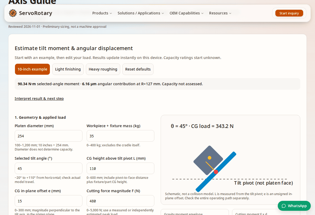
| Example | m / θ / L / e | F / d | Mg / Mc / combined (N·m) | Interpretation |
|---|---|---|---|---|
| 10-inch example | 35 kg / 45° / 110 mm / 15 mm | 480 N / 125 mm | 30.34 / 60.00 / 90.34 | At an assumed 10 arcsec bound and R=127 mm, angular term ≈6.16 µm. Request ratings. |
| Light finishing | 16 kg / 75° / 65 mm / 10 mm | 220 N / 90 mm | 10.26 / 19.80 / 30.06 | At an assumed 5 arcsec bound and R=127 mm, angular term ≈3.08 µm. Confirm drive duty if moving. |
| Heavy roughing | 68 kg / 30° / 140 mm / 25 mm | 920 N / 120 mm | 61.12 / 110.40 / 171.52 | Moment is higher despite a lower tilt angle. Reduce lever arms or request a suitably rated assembly. |
| Question | Reference / scope | Requested evidence |
|---|---|---|
| Individual-axis accuracy and repeatability | ISO 230-2:2014 public scope | Measured positioning/repeatability report, directions, range, thermal conditions and uncertainty; agree acceptance limits. |
| Coordinated tool/workpiece path | ISO 10791-6:2014 public scope; workpiece-side axes in Annex B | Test matching machine architecture, motion and feed conditions. Consult the agreed full standard; this guide does not reproduce its procedures. |
| Pivot alignment / setup health | Renishaw AxiSet manufacturer overview | Machine-specific probe cycle compatibility, baseline results and user-defined tolerances; distinguish a health check from full acceptance. |
| Thermal state and cutting performance | Application-specific acceptance agreement | Cold/warm/duty-cycle measurements and a representative cut. Cooling flow, temperature limits and part tolerance remain to be agreed. |
Scope sources: ISO 230-2, ISO 10791-6, Renishaw AxiSet. Public scopes were checked on 2026-11-01; full normative procedures and contract-specific thresholds are not independently verified here. No ISO conformity claim is made for this page or calculator.
| Risk | Consequence | Minimum action / alternative |
|---|---|---|
| Using a faceplate radius as every lever arm | Underestimated gravity or cutting moment | Locate the pivot and force line in CAD. Ask for a vector load review if geometry is unclear. |
| Static clamp credit during moving-axis cutting | Incorrect holding assessment | Use drive torque/RMS duty and following-error data. Consider indexed cuts if continuous motion is unnecessary. |
| Unknown power-loss holding behavior | Uncontrolled tilt movement | Request the exact brake/control specification and stopping review from the integrator; do not assume a positioning clamp is a safety brake. |
| Retrofit clearance or controller mismatch | Lost travel, collisions, unusable hardware | Obtain CAD swept-envelope and interface review. Compare a smaller frame or machine-native 5-axis option. |
| Assumed maintenance or lifecycle cost | Unplanned service and downtime | Use the exact service manual and quote parts/labor/downtime. Do not use generic backlash-adjustment instructions. |
| Cost block | Information to collect | Calculation / decision |
|---|---|---|
| Purchase & integration | Quoted assembly, controller options, cabling, guarding and commissioning | Total installed cost; currency and quote date required. No public verified ServoRotary price is available here. |
| Scheduled service | Model-specific lubricant, service intervals, labor and planned downtime | Sum service events over your actual annual hours. No generic 10,000-hour reset count is assumed. |
| Energy & cooling | Measured electrical/chiller power and operating hours | kW × hours × local energy rate. Confirm cooling requirements from the supplier. |
| Quality & availability | Representative-cut yield, cycle time, repair lead time and spares | Use a trial or contractual evidence. No unmeasured percentage improvement is credited. |
The query is ambiguous. It may mean a 10-inch faceplate; “10” alone does not establish a ±10 arcsec accuracy requirement. This page keeps both dimensions independent. Confirm units and the model drawing before requesting a quote.
No. Ten inches is 254 mm. A nominal 250 mm catalog size is nearby but has a different faceplate diameter. Pilot bores, slots, center height and mounting holes must be checked on the actual drawing.
No. Payload depends on the complete assembly, orientation, CG location and operating conditions. Use the model-specific horizontal/tilted load envelope and include the fixture mass. See the sourced model comparison below.
Measure L from the tilt pivot to the combined CG normal to the horizontal platen, including pivot-to-face height. The in-plane offset e is perpendicular to the tilt axis. Cutting arm d is the perpendicular distance from the tilt axis to the force line, not automatically the rotary faceplate radius.
For a 254 mm faceplate, R=127 mm and R×sin(10π/648000) gives about 6.16 µm. This is one geometric displacement term. It excludes runout, stiffness, thermal drift, pivot errors and other axes.
No. Resolution is the increment the encoder can distinguish. Accuracy and repeatability need a measured axis report with conditions and a stated test method. ISO 230-2 addresses individual-axis testing.
No. The 2× screen here is an illustrative planning assumption, not a standard. Ratings, pressure, shocks, compliance, combined loading, stopping and duty cycle all require a supplier review.
The moment and geometric displacement can still be calculated, but capacity is unknown. Blank ratings never turn into inferred capacities. Send the load case and request verified tilt-axis ratings at the intended operating conditions.
The positioning clamp is released while that axis moves. Continuous machining requires drive torque and thermal duty, servo stiffness and following-error checks. Switch the calculator mode to see this limitation beside the result.
Do not assume this from hydraulic or pneumatic clamping. Obtain the model-specific power-loss behavior, brake response, dynamic stopping capability and integration requirements. A static holding-torque figure alone does not establish these properties.
No. Use the manufacturer procedure for the exact model, adjustment mechanism and lubrication. A generic ring direction, torque value, backlash target or service interval can damage an assembly or invalidate its accuracy.
Provide the machine/controller model, enabled axis and TCP options, interface details, part/fixture CAD, swept envelope, load cases, duty cycle, utilities, target accuracy and an agreed acceptance plan. Compatibility and price remain unconfirmed until reviewed.
Published by ServoRotary. Sources accessed 2026-11-01. Catalog facts, public standard scopes and derived examples are separated above. Vendor pages are not independent performance tests. The linked editions identify the references consulted; agree the applicable edition and current specifications in the purchase contract.
Model-specific dimensions, tilt/rotary clamp torque, supply pressure, allowable payload and separate accuracy/repeatability data. Undated live catalog; specifications may change.
Official public scope: direct measurement of individual linear or rotary axes; simultaneous multi-axis testing is outside this method.
Official public scope: coordinated NC path accuracy. Annex B concerns configurations with two workpiece-side rotary axes. Consult the full agreed edition for test procedures.
Manufacturer explanation of pivot-point/alignment checks, machine-specific macros and user-defined tolerances; not a general machine accuracy guarantee.
Still unconfirmed: ServoRotary model-specific capacity, accuracy, controller compatibility, cooling, pricing, service intervals and power-loss response. Send your load case and machine details to obtain evidence before committing to a design.