
Hollow Bore Sizing and Cable Routing in Servo Rotary Actuators: Slip Rings, Rotary Unions, and Reliability Rules
Size hollow bores in servo rotary actuators: compare cable routing, slip rings and rotary unions, check torque and torsion, and prepare your engineering RFQ.
When specifying a servo hollow rotary actuator or precision rotary table, the central aperture—the hollow bore—allows pneumatic lines, vacuum tubing, sensor harnesses, and fieldbus cables to pass through the rotational center. Hollow bore sizing must account for the entire installed utility envelope, not just the sum of cable diameters.
The core takeaway: Select the routing architecture before selecting the bore. Unlimited rotation needs suitable rotary interfaces for the utilities being transferred. A limited reversing axis can use direct torsion-rated cables and hoses if their motion limits are validated. Check four interdependent factors:
- Clear aperture and packing: Check the smallest installed opening, connector envelopes, liners, and motion clearance. The 40% area-fill target used below is a preliminary layout assumption, not a universal standard.
- Seal and harness drag: Obtain component-specific torque data and include the resistance at the correct side of the gearbox.
- Mounting and alignment: Follow the selected union or slip ring's support and anti-rotation instructions; floating restraints apply where the model requires them.
- Cable and hose fatigue: Check maximum twist from the installed neutral position, free length, bend radius, temperature, and duty cycle together.
Reviewed October 31, 2026. Global English-language engineering selection guide. Calculations below use hypothetical inputs; no hardware life testing or customer performance results are claimed.
Have a utility list already? Request a routing-envelope review with your motion profile and minimum clear bore.
Scope, Method, and Decision Assumptions
This guide serves mechanical designers, electrical harness engineers, and OEM procurement teams working on indexing dials and rotary positioning axes. Its method is to compare routing architectures, screen area and torsion geometrically, calculate an illustrative output torque, and turn unresolved limits into written RFQ requirements.
The examples concern ordinary industrial air/vacuum and low-voltage power/data routing. The following are screening assumptions, not approved component operating ranges:
- Motion: Approximately 10–200 rpm, with the actual acceleration, dwell, reversals, and accumulated turns specified separately.
- Media: Clean compressed air around 5–8 bar gauge, vacuum around -70 to -85 kPa gauge, 24/48 VDC circuits, and industrial Ethernet. Pressure, vacuum, flow, electrical current, and data-rate ratings must be checked independently.
- Actuator: A central passage with roughly 28–100 mm nominal bore. Retainers, brackets, fittings, and protective sleeves may reduce its usable diameter.
- Environment: Ordinary indoor industrial conditions. Cleanroom, high-vacuum, hazardous-area, washdown, or chemically aggressive applications need separate component and compliance review.
This guide does not certify electrical installation, machine safety, cleanroom suitability, or service life. The cited manufacturers establish component principles and product options; they do not approve this hypothetical assembly.
Key Executive Takeaways for Procurement & Engineering
- Bore diameter is a packaging constraint: A union body, connector, or hose fitting can dictate the opening even when total cable area is small. Obtain section drawings showing installation and removal paths.
- Account for drag at the correct shaft: Union drag at the table output cannot be compared directly with a motor-shaft torque rating. Include breakaway, running resistance, and gearbox effects.
- Use the specified mounting arrangement: A self-supported union may require a floating torque restraint; other designs require different support. Do not apply a generic slot clearance to every model.
- Treat fill ratio as a screen: Passing the example's 40% target does not prove bend-radius compliance, heat dissipation, connector fit, or fatigue life.
- Validate power and data together: Inspect shielding and grounding, then record network errors during rotation and actual solenoid switching rather than relying on a cable-category label alone.
Visualizing Through-Bore Routing Architectures & Components
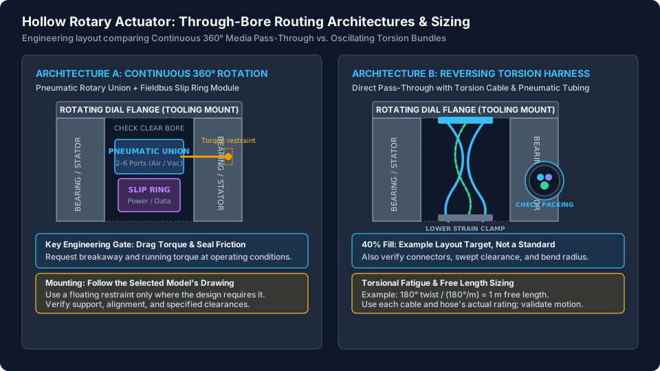
The primary choice is between unlimited rotation, using rotary electrical/fluid interfaces, and limited reversing motion, using a suitable torsion harness or a finite-travel external carrier.
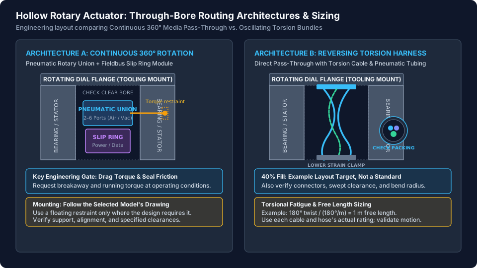
Figure 1: Conceptual routing layouts, not to scale or a mounting drawing. Left: rotary union and slip ring with model-specific torque restraint. Right: direct harness between rotating and stationary clamps. The 40% fill and torsion values shown are example screening inputs, not universal ratings.
The actuator's output bearing carries the tooling loads. Utility interfaces and hoses need their own approved support and strain relief; they must not become unintended structural load paths.
Detailed Utility Pass-Through Comparison Matrix
Compare architectures against the same motion and utility requirements before comparing price.
| Evaluation criterion | Slip ring & rotary union | Direct oscillating torsion harness | External rotary energy chain | RFQ & procurement verification gate |
|---|---|---|---|---|
| Motion capability | Suitable designs support unlimited rotation or multi-turn indexing | Limited reversing motion within the selected cable and hose limits | Finite angular travel set by the carrier model | Specify extrema, installed neutral position, reversals, speed, and duty. |
| Through-bore envelope | Include body OD, fittings, connectors, support, and installation access | Include actual bundle packing, liners, and moving clearance | May leave the bore free but needs external swept space | Obtain minimum clear diameter and a section drawing, not nominal bore alone. |
| Drag torque | Obtain breakaway and running curves for the selected media and conditions | Cable/hose restoring torque varies with angle and temperature | Include carrier resistance and moving mass | Refer all torque and inertia terms to a common shaft. |
| Electrical signal quality | Select an interface documented for the protocol and data rate | Continuous conductors avoid sliding contacts but still need EMC control | Continuous conductors need suitable flex rating and shielding | Validate the assembled link during rotation and load switching. |
| Air/vacuum capacity | Limited by passage flow, leakage, pressure, and seal compatibility | Limited by tube motion rating, bend radius, and pressure drop | More routing room may be available, subject to carrier limits | Request flow and cross-port leakage data at the required conditions. |
| Service and maintenance | Contact and seal wear depend on design and duty | Fatigue life depends on cable/hose selection and installation | Carrier and cable wear depend on motion and environment | Obtain model-specific maintenance intervals and a replacement procedure. |
| CAPEX and TCO | Quote the complete rotary interface and mounting package | Quote torsion-rated cables, hoses, terminations, and clamps | Quote carrier, cables, brackets, and installation space | Use comparable scope and explicit downtime assumptions; no generic price range applies. |
| Alignment sensitivity | Follow the model's concentricity, support, and restraint instructions | Avoid local pinching, clamp stress, and jacket rubbing | Follow carrier mounting and concentricity instructions | Record drawing revisions, clearances, and supplier acceptance before PO. |
Sizing Direct-Routed Torsion Harnesses for Oscillating Tables
A rotary indexing platform that reverses within a finite range may use a direct harness. Unlike a linear cable carrier, this arrangement subjects the bundle to torsion, often combined with bending. A continuous-flex rating alone does not establish torsion suitability.
1. Cross-Sectional Fill Ratio: A Preliminary Layout Target
For this guide's preliminary layout, use a 40% area-fill target to reserve space for routing. The cited sources do not establish it as a through-bore standard. A smaller allowable fill or a different arrangement may be needed for the chosen cables and hoses.
A_bore = pi * D_clear^2 / 4
A_utilities = sum(pi * d_i^2 / 4)
Fill ratio = A_utilities / A_bore
Example screening target: Fill ratio <= 0.40
Use the minimum installed clear diameter for D_clear, and include each cable or tube's outer jacket. For a common sleeve, use its outside envelope for packing rather than double-counting its contents. This area sum is only a lower-bound screen: irregular packing, connectors, entry radii, off-axis movement, and an installed union can dominate the real fit.
Check a sectioned CAD layout through the full motion range. If the assembly cannot meet supplier clearance and bend-radius requirements, enlarge the passage, change the routing architecture, or reduce the utility package.
2. Torsional Stress and Free Length Calculation
Select a cable specifically rated for the intended torsion, temperature, speed, and cycles. igus's robot-cable range describes torsion-capable designs, including ratings up to ±360° per meter for selected types; this is not a rating shared by all robotic cables.
As a preliminary calculation:
L_free_min [m] = theta_max_from_neutral [deg] / q_allow [deg/m]Here theta_max_from_neutral is the largest absolute twist away from the installed untwisted position, and q_allow is the selected cable's allowable torsion under the relevant conditions. For an assumed ±180°/m rating and a maximum 180° twist:
L_free_min = 180 / 180 = 1.0 m
At L_free = 0.4 m, the same screen permits 72 deg from neutral.
A sweep from -180° to +180° has 360° peak-to-peak travel but 180° maximum twist from a centered neutral position. Confirm the supplier's amplitude and test-cycle definitions before using either number. Every hose and cable in the bundle must pass its own motion check.
3. Strain Relief and Motion Validation
Secure the harness at the rotating and stationary ends using the cable supplier's clamp instructions. Keep the active torsion length free from unintended intermediate restraints. Avoid ties or spacers that concentrate twist; use any required separators or guides only as specified for the harness design.
Check tube ovalization, minimum bend radius, connector strain, abrasion at bore edges, and cable migration at both motion extremes. Passing the free-length calculation alone does not establish service life.
Pneumatic Rotary Unions: Flow, Vacuum, and Seal Drag Torque
Unlimited rotation cannot use an indefinitely twisting supply hose. Select a suitable fluid rotary interface for air or vacuum transfer. Passage count alone does not establish flow capacity: request pressure drop at the required flow, vacuum leakage, cross-port leakage, media compatibility, speed limits, and allowable mounting loads.
1. Multi-Passage Configurations and Port Sizing
Select independent passages for the required circuits. Confirm the actual thread standard, fittings, hose OD, and connector removal space; a small nominal port can still require a large fitting envelope. For mixed positive pressure and vacuum, ask how the selected unit limits cross-port leakage and how that leakage affects the gripper's minimum holding vacuum.
2. The Motor Sizing Adder: Seal Drag Torque
Obtain both breakaway torque and running drag at the applicable pressure, speed, temperature, seal condition, and media. There is no justified universal drag range in the references cited here.
A simplified output-side acceleration calculation is:
T_output = J_output * alpha_output + T_process + T_bearing + T_union + T_harnessSigns and magnitudes depend on motion direction. Check acceleration, reversal, and deceleration separately. Refer output loads through the ratio and efficiency before comparing with motor-shaft ratings. The continuous/RMS torque check needs the complete cycle, dwell behavior, and appropriate component loss model; peak output torque alone cannot select the motor.
Missing torque data is an unresolved RFQ requirement, not a reason to assume zero friction.
Anti-Rotation Restraints: Preventing Unwanted Bearing Loads
A rotary interface has a rotating member and a stationary member. For self-supported designs whose installation instructions require a floating housing, an anti-rotation restraint reacts friction torque while allowing the specified movement. Rigidly locating both members can transmit misalignment and table runout into the interface bearings and seals.
The appropriate arrangement depends on the exact model:
- Support and alignment: Follow the manufacturer's rotor attachment, housing support, concentricity, and runout requirements. A bearingless union can require a different support arrangement from a self-supported unit.
- Torque restraint: Where a slotted fork or torque pin is specified, use the drawing's radial/axial clearance and engagement dimensions. No universal 1–2 mm float value applies to every unit.
- Hose loads: Where flexible connections are required, select compatible, pressure-rated hoses with the specified bend radius. Support piping so its weight, strain, or thermal movement does not unintentionally locate the housing.
For FAT, check the full motion range for binding, restraint interference, hose strain, and abnormal torque. Obtain written installation approval for the proposed mounting arrangement before releasing the assembly.
Electrical Slip Rings: Fieldbus Integrity and Noise Segregation
A slip ring transfers electrical power and signals between stationary and rotating structures. Specify the actual circuit inventory: supply voltage and current, inrush, analog/digital signals, protective bonding requirements, network protocol, data rate, and environmental limits.
1. Contact Design and Protocol Suitability
Choose contact metallurgy and brush construction from the manufacturer's low-level signal, current, wear, and noise specifications. Precious-metal contacts can suit low-level signals, but gold contacts alone do not guarantee zero dust, cleanroom approval, or error-free Ethernet.
Request the definition and test conditions for dynamic resistance variation, permitted speed, and wear life. For Ethernet, obtain evidence for the complete rotary interface and connector arrangement at the required data rate. Separate approval is needed for safety-related signals or functions.
2. Cross-Talk and EMC Transients
Solenoid switching can couple disturbances into neighboring signal circuits. The transient magnitude and resulting communication behavior depend on the coil, suppression, wiring, grounding, and interface design; no fixed voltage spike or automatic safety response is assumed here.
- Separate switching power and sensitive data paths using the selected interface's approved layout.
- Follow coil and output-module instructions for suppression. A diode or TVS choice can affect release time and must suit the application.
- Preserve the specified shield continuity and connector termination, including 360° shield bonding where required.
- During FAT, log network errors while rotating at the required speeds and switching the real loads. Test across the relevant operating conditions rather than approving the link from a static continuity check.
Use the procurement checklist below to capture the evidence still needed from each supplier.
Mathematical Sizing Framework: Fill Ratio, Free Length, and Motor Torque
This hypothetical worked example separates two alternatives. Steps 1–2 screen a direct harness. Step 3 illustrates torque if a rotary union is selected; its body needs a separate packaging check. Do not assume the union and every tube in the direct-harness example fit together in the same opening.
Assumed inputs:
- Minimum clear bore: 62.0 mm after installed obstructions; not a verified catalogue dimension or frame-size recommendation.
- Motion leg: 0° to +180° in 0.60 s, then return; the harness is installed untwisted at 0°. A -180° to +180° leg would require a different motion calculation.
- Output inertia: 0.085 kg·m², assumed to include table, fixtures, payload, and any rotating interface parts.
- Utilities: One 6.8 mm OD EtherCAT cable, two 4.5 mm OD sensor cables, one 7.2 mm OD power cable, and four 6.0 mm OD tubes.
- Union alternative: Four passages at an assumed 6 bar gauge supply; no manufacturer's torque or flow rating is implied.
Step 1: Calculate Through-Bore Cross-Sectional Fill Ratio
A_bore = (pi / 4) * 62.0^2 = 3,019.07 mm^2

A_ethercat = (pi / 4) * 6.8^2       = 36.32 mm^2
A_sensors  = 2 * (pi / 4) * 4.5^2   = 31.81 mm^2
A_power    = (pi / 4) * 7.2^2       = 40.72 mm^2
A_tubing   = 4 * (pi / 4) * 6.0^2   = 113.10 mm^2
A_total_utilities = 221.95 mm^2

Fill ratio = 221.95 / 3,019.07 * 100% = 7.35%
Evaluation: 7.35% is below the example's 40% screening target. It does not prove connector fit, cable temperature, swept clearance, or an acceptable bend radius. Add sleeves, fittings, and support geometry to the CAD check before approving the bore.
Step 2: Determine Free Length for Oscillating Motion
With an assumed allowable torsion of ±180°/m and 180° maximum twist from neutral:
L_free_min = 180 deg / (180 deg/m) = 1.0 mIf only 600 mm is available, that assumed rating permits at most 108° from neutral under this simple screen. Dividing a 180° move into two 90° moves in the same direction does not reset accumulated twist.
A different cable explicitly rated for ±360°/m under the required conditions would give:
L_free_min = 180 deg / (360 deg/m) = 0.50 mThe 500 mm result fits the assumed 600 mm free-length allowance geometrically. It does not approve the hoses, terminations, or assembly fatigue life. Check those limits separately, or change the neutral position, motion, or routing architecture.
Step 3: Calculate Dynamic Motor Torque Including Seal Drag
Assume a rest-to-rest triangular velocity profile for a 180° move in 0.60 s, with equal acceleration/deceleration time and no cruise:
theta = pi rad
t_acc = t_dec = 0.30 s
alpha = 4 * pi / 0.60^2 = 34.91 rad/s^2
omega_peak = alpha * 0.30 = 10.47 rad/s = 100 rpm
T_inertial_output = 0.085 * 34.91 = 2.967 N*m
For arithmetic only, assume running union drag of 1.50 N·m and bearing friction of 0.40 N·m, both at the output. Process and harness torque are set to zero for this simplified alternative and must be restored if present:
T_acceleration_output = 2.967 + 0.40 + 1.50 = 4.867 N*m

Assumed reduction ratio i = 10:1
Assumed forward-driving efficiency eta = 0.90
T_motor_load_component = 4.867 / (10 * 0.90) = 0.541 N*m
Engineering interpretation: The assumed union drag is 30.8% of this acceleration torque. The 0.541 N·m result is only the load-related motor torque component, not an approved peak or continuous motor rating. Add motor/reducer inertia, breakaway torque, process loads, margin, and the actual motion profile; check deceleration, RMS torque, and thermal limits. Real servo profiles may use jerk limits rather than this ideal triangular profile.
Failure Modes When Through-Bore Integration Is Undersized or Misaligned
Use these possible symptoms to guide FAT investigation; they are not unique diagnoses or measured failure predictions:
- Interface misalignment or incorrect support: Binding, abnormal running torque, seal leakage, or bearing noise. Check the installation drawing, piping loads, alignment, and torque restraint.
- Bundle packing or edge contact: Jacket scuffing, tube wear, or motion-dependent friction. Inspect the full swept envelope; a percentage fill threshold alone cannot diagnose the cause.
- Excess torsion or short active length: Cable migration, insulation distortion, or intermittent continuity. Compare actual twist and clamping with each cable and hose specification.
- EMC or data-link problems: Network errors correlated with rotation or switching. Check shielding, grounding, suppression, link qualification, and connector strain before attributing faults to the slip ring.
Record the test configuration, speed, pressure, temperature, inspection findings, and error counts. A short acceptance run can identify integration faults but cannot substantiate multi-million-cycle life.
Total Cost of Ownership (TCO): Slip Rings vs. Torsion Cable Assemblies
First confirm both options can satisfy the required motion. A direct harness is not a substitute for a rotary interface on an unlimited-rotation axis.
TCO = purchase + installation + planned service + replacement + downtime costFor production exposure, 16 hours/day × 250 days/year equals 4,000 operating hours/year. At one complete machine cycle every 3 seconds, this is 4.8 million cycles/year, or 9.6 million cycles over two years. Machine cycles are not automatically union revolutions or cable torsion cycles; define the travel and reversal count separately.
The following is an illustrative USD budget sensitivity, not supplier pricing or observed reliability. Assume a limited reversing application where either architecture could qualify. Exclude the identical actuator from both options and compare utility packages with the same installation scope:
- Option A, rotary interface package: Assumed initial installed cost $1,400 plus one assumed $450 planned service event over two years gives $1,850, before any other replacement or downtime cost. The service event is a budget assumption, not a recommended interval.
- Option B, qualified direct torsion harness: Assumed initial installed cost $750. Its two-year service, replacement, and downtime costs remain unknown until supplier data and the maintenance plan are available.
- Downtime sensitivity: One hypothetical 6-hour interruption at an assumed $500/hour costs $3,000 in lost production, excluding repair parts/labor. This is not a predicted harness failure.
- Break-even screen: The $650 initial difference equals 1.3 hours at $500/hour. Including Option A's assumed service event makes its assumed $1,100 cost difference equal 2.2 hours, before Option B's service costs. Neither result establishes which design will fail or cost less.
Procurement takeaway: Compare qualified designs using quoted costs and explicit service/downtime assumptions. Request replacement-access drawings and maintenance data rather than accepting generic cycle-life or payback promises.
Procurement & Engineering Verification Checklist
Before issuing a PO for a servo hollow rotary table, close the following requirements in writing:
- Clear aperture: Obtain a dimensioned section showing the minimum installed opening, retainers, fittings, liners, and connector installation/removal paths.
- Bundle envelope: Calculate cable/tube area, document any preliminary fill target, and validate actual packing, swept clearance, bend radii, and temperature limits in CAD and the assembly.
- Motion definition: Specify angular extrema, installed neutral position, accumulated turns, speed, acceleration, dwell, and reversal/cycle definitions.
- Torque data: Obtain breakaway and running drag at the required conditions. Include all output loads and inertias, reflect them to the motor correctly, and check peak/RMS limits.
- Mounting acceptance: Confirm the exact rotor attachment, stator support, alignment tolerances, and any floating restraint clearances against the chosen model's drawing.
- Media and hoses: Verify pressure/vacuum, flow, cross-port leakage, materials, hose motion rating, connection loads, and safe retention of the workpiece under loss of supply.
- Torsion qualification: Check each cable and hose at the actual twist, free length, bend radius, temperature, and required cycles. Do not substitute a continuous-flex rating for a torsion rating.
- Electrical validation: Verify current/inrush, protocol/data rate, shielding, bonding, and suppression. Record link errors during motion and actual load switching.
- Service access: Demonstrate a replacement procedure, spares list, inspection interval, and realistic labor/downtime estimate without assuming a generic service life.
Frequently Asked Questions
What is the maximum recommended cable fill ratio for a hollow rotary actuator through-bore?
There is no universal through-bore fill limit established by the sources cited here. This guide uses 40% as a preliminary layout target, not a standard or an approval criterion. Verify actual bundle packing, connector clearance, bend radius, torsion, temperature, and the selected suppliers’ installation limits.
How much drag torque does a pneumatic rotary union add to a servo hollow rotary table?
Use the selected union’s breakaway and running torque data at the specified pressure, speed, temperature, and media. The 1.50 N·m value in this guide is an assumed example input, not a typical rating. Refer output-side drag through the reduction ratio and efficiency before comparing it with motor torque.
Why might a rotary union or slip ring need a floating anti-rotation restraint?
For a self-supported unit whose installation drawing calls for a floating housing, the restraint reacts torque while allowing the specified movement. Rigidly locating both rotor and housing can impose unwanted loads from misalignment. Follow the exact model’s mounting method; there is no universal float clearance for all unions or slip rings.
When should I use a slip ring versus a direct torsion-rated flexible cable harness?
For unlimited rotation, use a suitable electrical rotary interface and a fluid rotary union when those utilities are needed. For limited reversing motion, a torsion-rated harness can avoid sliding electrical contacts if its angle, free length, bend radius, hose rating, and duty cycle are validated. Neither architecture has a universal reliability advantage.
How do you calculate the minimum free length for oscillating torsion cables?
As a preliminary screen, divide the maximum twist from the installed neutral position in degrees by the selected cable’s allowable torsion in degrees per meter. A 180-degree twist at 180 degrees per meter needs 1.0 meter; at 360 degrees per meter it needs 0.5 meter. These are conditional examples, not universal cable ratings or life guarantees.
Can EtherCAT or PROFINET industrial Ethernet signals share a through-bore with solenoid power cables?
They can share a bore when the selected cables or rotary interface support the protocol, data rate, shielding, and installation environment. Separate switching power and data paths, follow grounding and suppression instructions, and validate network errors while rotating and switching the real loads. A Cat5e/Cat6 label alone does not approve the assembled link.
What can happen if rotary union connections impose rigid pipe loads?
Pipe strain can load the housing, disturb alignment, and contribute to bearing or seal wear. Where the selected union requires flexible connections, use compatible, pressure-rated hoses with the specified bend radius and independent support. Follow the model-specific installation drawing rather than imposing one hose material on every application.
How does through-bore cable routing affect maintenance and total cost of ownership?
Access to the center assembly affects inspection and replacement labor. Compare quoted component costs, supplier maintenance intervals, replacement access, and downtime assumptions for architectures that meet the same motion requirements. The cost example here is a sensitivity calculation, not a measured service-life or downtime result.
Sources and Technical Verification Notes
Review date: October 31, 2026. These official manufacturer resources support the component principles indicated below. They are product resources, not independent test reports or approval of the example assembly.
- Oriental Motor — DGII Series Hollow Rotary Actuators: Manufacturer product reference for hollow output tables and cable/tubing routing. The product entry is identified by the manufacturer's DGII announcement; automated access to the original cited Oriental Motor address was restricted during this review. Obtain the current model drawing directly before using dimensions.
- igus — chainflex Robot Cables: Manufacturer description of torsion-capable cable construction and selected types with torsion capability up to ±360°/m. Confirm the specific part number and test conditions; this page does not establish a universal 40% bore-fill rule.
- Moog — Slip Rings: Manufacturer explanation of power/signal transfer between stationary and rotating structures, slip-ring options, and resistive-noise considerations. The overview does not establish the electrical or life rating of a selected assembly.
Evidence boundary: The 40% layout target, 62 mm bore, 1.50 N·m drag, bearing friction, efficiency, and USD costs are explicit example assumptions. Arithmetic is reproducible from the inputs shown. No cited overview verifies generic union float clearance, seal drag, cycle life, cleanroom suitability, or replacement time. Obtain model-specific documentation and application validation for those decisions.
Recheck this guide when component drawings, motion requirements, cable ratings, or supplier maintenance instructions change.
Review Your Rotary Table Utility Envelope Before Sizing
Contact our application engineering team with the minimum clear bore, sectioned assembly layout, dial diameter, payload inertia, motion profile, cable/tube inventory, pressure/flow requirements, and fieldbus protocol. Request a documented fit and sizing review with any missing supplier limits identified before PO.
Compare the available hollow rotary actuators and precision rotary tables against that utility envelope and your required service access.
Author

Categories
More Posts
2026-W23 Servo Rotary Sourcing Tariff Gate
Week-23 buyer brief for servo hollow rotary tables: U.S. metal-tariff changes, trade-flow pressure, bore/load selection boundaries, and PO-release actions.
Direct Drive vs Servo Hollow Rotary Tables: A Procurement and TCO Comparison
Direct Drive Rotary vs Servo Hollow Rotary Tables for precision indexing: compare backlash, inertia, tuning effort, lead-time risk, and TCO before RFQ.
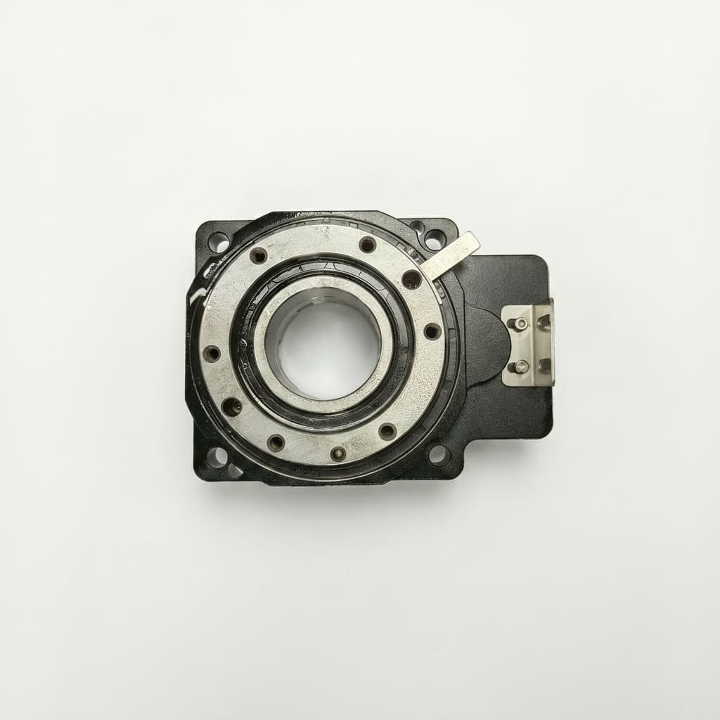
Pneumatic vs. Servo Hollow Rotary Tables: A TCO and Performance Procurement Guide
A comprehensive lifecycle and Total Cost of Ownership (TCO) analysis comparing pneumatic indexing tables with servo-driven hollow rotary tables for procurement and engineering teams.