
Cycloidal (RV) vs. Harmonic (Strain Wave) vs. Precision Planetary in Servo Rotary Actuators: Shock Capacity, Lost Motion, Backlash Drift, and 20,000-Hour TCO
Compare servo rotary actuators by shock limits, lost motion, backlash drift, and 20,000-hour TCO. Use the engineering checklist to prepare your next supplier RFQ.
When machine builders and OEM procurement teams specify a servo rotary actuator, the internal reducer affects torque capacity, reversal behavior, packaging, and operating cost. Cycloidal (RV), harmonic (strain wave), and precision planetary designs can all be appropriate. A technology label cannot replace a model-specific duty-cycle calculation.
Quick selection answer: shortlist cycloidal RV units for demanding load support and shock exposure; strain wave units for compact, high-ratio joints; and precision planetary units for efficient, economical transmission where the specified reversal accuracy is adequate. Then compare complete actuators at the same load, ratio, speed, temperature, and positioning requirement. Direct drive is a useful non-geared reference when transmission compliance dominates the application.
Use the acceptance checklist below to build an RFQ, or discuss your duty cycle with our application team before choosing a frame size.
Reviewed November 12, 2026. Scope: global industrial rotary indexing and positioning applications. This is a supplier-document comparison with illustrative calculations, not a physical endurance test, a safety standard, or a guarantee for any product. Prices, wear allowances, and settling targets below are stated assumptions.
1. Scope, Engineering Assumptions, and Mechanical Boundaries
This guide compares reducers integrated into servo rotary actuators and indexing tables. It addresses engineering and purchasing decisions from the first shortlist through purchase-order acceptance. The primary use case is a reversing index-and-dwell axis carrying a dial plate, fixture, or robotic joint. Continuous machining, vacuum operation, explosive atmospheres, and human-contact robotics require additional application-specific qualification.
The three geared architectures are cycloidal RV pin-wheel reducers, strain wave flexspline reducers, and precision planetary gearboxes. Direct Drive Rotary (DDR) torque motors provide a fourth, non-geared reference. Compare the entire assembly: motor, ratio, reducer, output bearing, encoder, mounting, brake, and controller. A bare reducer's torque or backlash rating does not establish the actuator's allowable tilting moment or accuracy at the tool.
The economic horizon is 20,000 operating hours, equivalent to five years at 4,000 hours per year. This is a planning interval, not a claimed service life. For each quotation, request a load-spectrum life calculation and distinguish gear life, bearing life, lubricant intervals, and allowable precision loss.
Comparison method: identify the manufacturer's parameter definitions; normalize output-side units; calculate load torque and stiffness sensitivity; then compare costs using explicit scenario inputs. The incremental value is the RFQ and acceptance method, with reproducible arithmetic. No serial-numbered test data or field failure distribution is available for this article.
2. Drivetrain Dilemma: Kinematic Architectures and Contact Mechanics
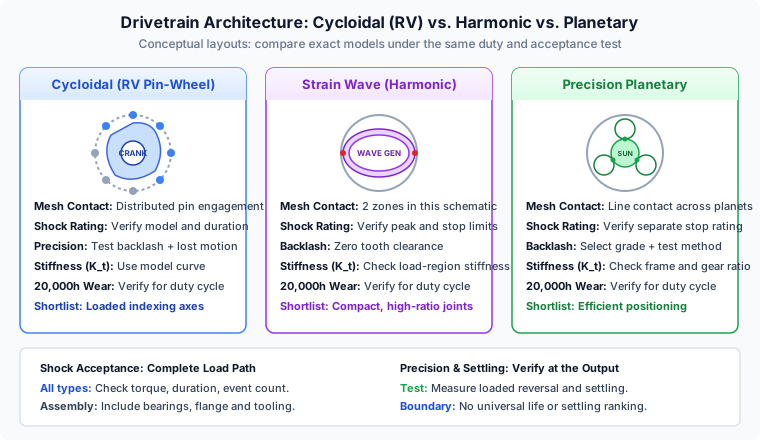
2.1 Cycloidal RV Reducers: Distributed Pin Engagement
An RV-style reducer commonly uses an input gear stage, eccentric crankshafts, and cycloidal discs engaging a surrounding pin ring. Multiple contacts distribute load, making this architecture a useful candidate for heavily loaded positioning axes. It still has contact stress, bearing loads, lubrication requirements, and finite fatigue life. It is inaccurate to describe the entire mechanism as pure rolling contact or immune to fracture.
Nabtesco's product guide, printed pages 7–8, describes distributed contact and advertises shock resistance of five times rated torque for relevant RV products, with model exceptions. Treat that statement as a shortlist signal; use the exact model's momentary torque and installation limits for approval. Mass, input inertia, breakaway torque, and total envelope also matter.
2.2 Strain Wave (Harmonic) Gearing: Elastic Flexspline Deformation
The conventional strain wave mechanism contains a wave generator, flexspline, and circular spline. Elastic deformation maintains tooth engagement and provides high reduction in a compact package. It can offer zero tooth backlash while still exhibiting elastic wind-up and hysteresis in the complete transmission.
Harmonic Drive's technology explanation describes these components, preload, and hollow-shaft options. Its newer three-zone technology also illustrates why an older two-zone sketch cannot define every strain wave product. Evaluate the selected series' stiffness curve, repeated peak torque, lubrication, and life calculation. There is no defensible universal ratcheting threshold expressed as one multiple of nominal torque for all sizes and ratios.
2.3 Precision Planetary Gearboxes: Sun, Planets, and Ring
Planetary reducers share torque through planet gears between a sun and ring. Precision products may use straight or helical teeth; neither form alone establishes the assembled backlash grade. Efficiency, ratio, bearing support, and available output flanges can make planetary transmission attractive for high-cycle machinery.
As a specific catalogue example, Neugart's PLFN technical table lists 96–97% efficiency, standard backlash below 3–5 arcminutes, and reduced-backlash options below 1 or 2 arcminutes depending on frame. Those are PLFN specifications, not industry-wide bounds. Compare the selected frame and ratio, including the stated operating conditions, rather than assigning every planetary gearbox the same accuracy.
2.4 Direct Drive Rotary: The Non-Geared Baseline
Direct drive removes the reduction gear and its backlash. It does not remove encoder error, torque ripple, output-bearing wear, fixture compliance, or thermal growth. Holding torque and acceleration must come directly from the motor and drive; cooling and a suitable encoder can become major design requirements.
Use DDR as a benchmark where eliminating transmission compliance may justify the installed cost. A claim of infinite life, zero maintenance, or guaranteed sub-5-millisecond settling would require evidence that is not available here.
3. Backlash vs. Lost Motion vs. Elastic Deflection
3.1 Define the Measurement Before Comparing Quotes
In ordinary engineering use, backlash refers to clearance revealed on reversal. Manufacturer hysteresis tests can define it as the angular width at zero applied torque after loading and unloading. Record the test procedure, input restraint, applied torque, temperature, and measuring location. Comparing a lightly loaded clearance test with a loaded hysteresis measurement can produce a misleading ranking.
Nabtesco's glossary on printed page 60 of the product guide defines lost motion in the ±3% rated-torque region with the input fixed, and backlash at zero torque. Other suppliers may specify different methods. Put the agreed low-load torque band and acceptance limit into the RFQ rather than assuming the term means the same thing across catalogues.
3.2 Separate Elastic Twist from Clearance
For an approximately linear operating region, output twist is deflection = applied torque / torsional stiffness. If an illustrative reducer has Kt = 90 N·m/arcmin, a 200 N·m load produces 200 / 90 = 2.22 arcmin of elastic twist. This is not 2.22 arcmin of backlash.
A non-linear stiffness curve requires the correct load region or a piecewise calculation. Include the compliance of couplings, bearings, bolted joints, and the table itself. An output encoder can help correct steady positioning error, but it does not remove mechanical deflection or make the disturbance response instantaneous.
3.3 Translate Angular Error into Tool Error
At a 250 mm working radius, one arcminute is approximately 0.25 × π / 10,800 = 72.7 µm of tangential displacement. An assumed 2 arcminute reversal allowance therefore corresponds to about 145 µm at that radius, before other errors. This conversion gives procurement a concrete reason to reject a nominally inexpensive unit when the process requires much tighter tool positioning.
Specify unidirectional repeatability, bidirectional positioning, and loaded compliance separately. A high-resolution motor encoder does not establish these output-side quantities.
4. Emergency Stops, Collisions, and Shock Torque Capacity
4.1 Calculate an Initial Output-Side Torque Demand
For an ideal rigid-body deceleration, T = J × Δω / Δt. Consider an illustrative total output-side inertia of 0.45 kg·m² rotating at 60 rpm and brought to rest in 20 ms. Angular velocity is 6.283 rad/s, so average inertial torque is 0.45 × 6.283 / 0.020 = 141.4 N·m.
This is an average screening value. Peak contact torque can be higher because of jerk, backlash take-up, fixture elasticity, brake engagement, and a collision's short contact duration. Add gravity and process loads where applicable. The calculation alone cannot approve a crash stop.
4.2 Compare the Correct Limits
Require separate continuous, repeated acceleration, momentary, and emergency-stop ratings. A five-times nominal RV headline cannot be compared directly with a planetary cyclic rating or a strain wave repeated-peak rating. Ask for permitted duration, speed, temperature, and lifetime event count for the exact part number.
Ratcheting, tooth damage, bearing damage, and fastener or fixture failure are possible overload outcomes. Their order depends on the assembly. A strain wave design can be suitable for an axis with emergency stops when its documented limits and complete stopping system are adequate. An arbitrary inertia threshold is not a sound exclusion rule.
4.3 Approve the Complete Load Path
Check the output bearing, hub, key or clamp, mounting bolts, and attached table as well as the reducer. Motor current limiting may not cap a collision torque imposed externally at the output. Stopping performance, protective measures, and any torque limiter need machine-specific engineering review; the gear comparison does not certify a safety function.
5. 20,000-Hour Wear Mechanics and Backlash Drift
5.1 Use a Load Spectrum, Not a Technology-Wide Wear Curve
Operating hours do not uniquely specify fatigue exposure. Twenty thousand hours at one index per second represents 72 million indexes; ten indexes per minute represents 12 million. Reversals, load peaks, lubricant condition, contamination, and temperature affect the result.
Planetary tooth wear can increase clearance, but a claim of 50–150% drift for every planetary product is unsupported. Cycloidal units also have finite bearing and contact life. Strain wave units require application-specific flexspline and bearing-life assessment; being below nominal torque does not establish infinite life for the whole actuator.
5.2 Define an End-of-Life Precision Limit
Set a process limit in output angle or tool displacement. For example, an assumed 150 µm tangential limit at a 250 mm radius equals about 2.06 arcminutes. That budget must cover the relevant positioning error, load-induced deflection, and thermal contribution; it cannot all be allocated independently to backlash.
Measure the warmed assembly at commissioning and agreed service intervals using the same payload, applied torque, direction sequence, and instrumentation. Record runout and breakaway torque separately. A single encoder readout at the motor cannot demonstrate that the table still meets its tool-position tolerance.
5.3 Request Evidence That Matches the Duty
Ask for a life calculation, lubricant schedule, and any endurance results under a comparable spectrum. Identify whether a supplier's number describes bearing fatigue, gear strength, or accuracy retention. If evidence is absent, mark the service-life precision estimate as unknown and price a sensitivity case; do not convert an assumed replacement event into a predicted failure rate.
6. Multi-Drivetrain Engineering Comparison Matrix
This matrix is a shortlist guide. Every quantitative acceptance value belongs to an exact model, ratio, and test method; the architectures do not establish a universal winner.
| Selection dimension | Cycloidal (RV) | Strain wave (harmonic) | Precision planetary | Direct drive reference |
|---|---|---|---|---|
| Torque production | Reduction through discs and pins | Reduction through deforming spline | Reduction through sun and planets | Motor supplies output torque directly |
| Reversal accuracy | Request backlash and lost-motion test | Zero tooth backlash can coexist with compliance | Select backlash grade and test method | No gear backlash; measure complete axis error |
| Stiffness comparison | Obtain curve for exact frame and ratio | Obtain load-region stiffness curve | Obtain frame- and ratio-specific value | Evaluate mechanical and closed-loop stiffness |
| Shock acceptance | Verify momentary torque and event limits | Verify peak limits and overload behavior | Separate cyclic, maximum, and stop torque | Check drive, bearings, structure, and brake |
| 20,000-hour precision | Require duty-based evidence | Require duty-based evidence | Require duty-based evidence | Check bearing, encoder, and thermal behavior |
| Efficiency comparison | Use operating-point loss data | Use operating-point loss data | Use stage- and load-specific data | Compare motor and drive losses at system level |
| Through-bore packaging | Hollow and solid variants exist | Hollow-shaft variants exist | Conventional center input restricts routing | Hollow configurations depend on motor design |
| Load support | Verify output bearing and tilting moment | Verify integrated bearing or external support | Verify flange and bearing arrangement | Verify bearing and motor integration |
| Settling acceptance | Measure loaded output | Measure loaded output | Measure loaded output | Measure loaded output |
| Useful shortlist case | Loaded indexing and shock exposure | Compact, high-ratio joints | Efficient general positioning | Applications sensitive to gear compliance |
7. Through-Bore Packaging and Geometry
A conventional solid-input, in-line planetary arrangement occupies the centerline. It may be unsuitable for a large uninterrupted cable bore, but this does not make every planetary-based hollow design physically impossible. Alternative motor placements and transmission layouts must be judged from the actual section drawing and installed envelope.
Hollow RV and strain wave variants can provide central routing, but neither architecture guarantees a particular bore-to-diameter ratio. Confirm clear diameter through the entire installed stack, including the motor adapter, brake, encoder, seals, and mounting plate. A nominal reducer bore is not necessarily the usable assembly bore.
List cable connector dimensions, tube bend radius, relative rotation, strain relief, and service access. Continuous rotation may require slip rings or rotary unions; routing a cable through the center alone does not permit unlimited turns. Review these details with the hollow bore sizing and cable routing guide.
If packaging is the deciding constraint, compare hollow rotary actuator configurations against a dimensioned cable bundle before optimizing gearbox cost.
8. Settling Time, Resonant Frequency, and Automation Throughput
8.1 Use Stiffness to Screen Mechanical Frequency
A simplified two-inertia model connects motor inertia reflected to the output, JM × i², to load inertia JL through torsional stiffness Kt. With stiffness in N·m/rad, the undamped load-side anti-resonance estimate is:
far = sqrt(Kt / JL) / (2 × π)
fr  = sqrt(Kt × (1 / JL + 1 / (JM × i²))) / (2 × π)
1 N·m/arcmin = 3437.75 N·m/rad
These estimates assume a linear spring and lumped inertias. Additional structure modes, damping, gear inertia, and controller dynamics can change the response. Do not equate either calculated frequency with closed-loop bandwidth or a settling-time guarantee.
8.2 Corrected 500 mm Dial Table Example
Assume a 500 mm dial, total load inertia JL = 0.45 kg·m², and two hypothetical stiffness values. These values represent a sensitivity comparison, not measured or matched commercial actuators.
| Illustrative input or result | Candidate A | Candidate B |
|---|---|---|
| Stiffness, N·m/arcmin | 10 | 85 |
| Converted stiffness, N·m/rad | 34,377 | 292,208 |
| Load inertia, kg·m² | 0.45 | 0.45 |
| Calculated anti-resonance, Hz | 44.0 | 128.3 |
| Tangential acceptance band at 250 mm radius | ±15 µm | ±15 µm |
| Equivalent angular band | ±12.4 arcseconds | ±12.4 arcseconds |
| Measured settling time | Not available | Not available |
For Candidate A, sqrt(34,377 / 0.45) / (2 × π) = 44.0 Hz; Candidate B gives 128.3 Hz. These frequencies cannot determine the damping or settle duration. The supplied load inertia must also be checked against the actual plate, fixtures, and workpieces.
8.3 Verify Throughput at the Output
If a 60° move takes 250 ms, assumed settling delays of 160 ms and 25 ms yield 410 ms and 275 ms motion-plus-settling intervals. With one completed part per index and no additional process dwell, theoretical rates are 60 / 0.410 = 146.3 and 60 / 0.275 = 218.2 parts/min. The difference is 49.1% only under those assumed delays and cycle boundaries.
These are arithmetic scenarios, not observed technology advantages. Include inspection dwell, handling, yield, and overlapping operations before using throughput in a quotation. Accept the axis using an output encoder or suitable displacement measurement at the tool, with the actual payload and acceptance band. See the related torsional stiffness and dial plate settling guide for additional sizing context; its examples also require project-specific validation.
9. 20,000-Hour Total Cost of Ownership Model
The following undiscounted USD planning scenario preserves a common purchasing comparison while exposing every assumption. It is not a price survey, warranty, field reliability study, or prediction of which technology will fail. Replace all entries with supplier quotes and plant data before making a purchase decision.
The model covers 20,000 operating hours. Commissioning and maintenance labor are valued at $100/hour. Foregone sellable capacity is valued at an assumed $30/hour; it is relevant only when the line is capacity-constrained and the lost output can actually be sold. Energy is valued at $0.15/kWh. Taxes, financing, freight, residual value, and common machine costs are excluded.
| Scenario cost input | Planetary candidate | Strain wave candidate | Cycloidal candidate | Direct drive candidate |
|---|---|---|---|---|
| Assumed actuator hardware and flange | $1,200 | $2,400 | $2,100 | $4,800 |
| Assumed motor and drive budget | $900 | $900 | $1,050 | $2,200 |
| Commissioning: 3 / 6.5 / 3.5 / 8 labor hours | $300 | $650 | $350 | $800 |
| Lost capacity: 60 / 180 / 20 / 0 equivalent hours | $1,800 | $5,400 | $600 | $0 |
| Inspection and recalibration: 15 / 4 / 2 / 0 hours | $1,500 | $400 | $200 | $0 |
| Hypothetical replacement allowance | $1,600 | $3,200 | $0 | $0 |
| Energy: 3,000 / 4,333.33 / 3,666.67 / 5,000 kWh | $450 | $650 | $550 | $750 |
| Illustrative total, rounded USD | $7,750 | $13,600 | $4,850 | $8,550 |
Reproduction: add the seven cost rows. For the cycloidal candidate, 2100 + 1050 + 350 + 600 + 200 + 0 + 550 = 4850. Capacity loss is the $30/hour rate multiplied by the stated equivalent lost hours. The energy figures are assumed system consumption, not deductions from gearbox efficiency. For an integrated actuator quote, allocate costs once; do not count an included motor again.
Sensitivity: excluding lost-capacity and replacement allowances gives $4,350 planetary, $5,000 strain wave, $4,250 cycloidal, and $8,550 direct drive. If the hypothetical cycloidal candidate then needs a $1,600 replacement, its total becomes $5,850 and exceeds the planetary case. This reversal demonstrates why the original assumptions matter more than a technology-wide ranking.
Zero allowances mean that the scenario has budgeted nothing for that line; they do not mean zero physical wear or guaranteed survival. Do not count the same unavailable hours both as throughput loss and replacement downtime. Add probability-weighted failure cost only when defensible reliability data exist. There is no supported nine-month payback claim here.
10. Sizing, Procurement, and PO Acceptance Checklist
Require the supplier to return the following with its quotation. Record the exact revision of the drawing and datasheet used for acceptance.
- Architecture and configuration: identify reducer series, frame, ratio, motor, encoder location, output bearing, brake, and lubrication.
- Duty profile: provide inertia, payload center of gravity, axis orientation, process torque, move angle, move time, dwell, reversals, ambient conditions, and hours per year.
- Torque limits: compare continuous duty, repeated peaks, and emergency events using the supplier's separate limits, durations, and event counts.
- Reversal precision: specify backlash and lost-motion definitions, applied test torque, temperature, input restraint, and maximum permitted output error.
- Compliance and settling: request load-region stiffness data and demonstrate the loaded tool reaches its acceptance band within the allocated time. Set the frequency target from the actual control design, not an arbitrary plate diameter.
- Life and maintenance: obtain the duty-based life calculation, lubrication schedule, precision-retention evidence, spare-unit lead time, and agreed inspection intervals.
- Bore and mounting: verify clear routing through the installed stack, bend radii, rotary service interfaces, load support, flange, and fasteners.
- Factory acceptance evidence: request serial-numbered measurements of agreed bidirectional positioning, loaded deflection, runout, breakaway torque, and settling. Use suitable procedures for each quantity; one positioning standard does not cover every measurement.
11. Frequently Asked Questions
What is the difference between backlash and lost motion in a servo rotary actuator?
Backlash describes reversal clearance or the zero-torque hysteresis width under a stated test method. Lost motion includes low-load compliance; Nabtesco measures it in the ±3% rated-torque region with the input locked. Zero tooth backlash does not guarantee zero output deflection or positioning error.
Can a strain wave reducer be used where emergency stops occur?
Yes, if the exact model is approved for the stopping torque, speed, duration, event count, and load path. Ratcheting is a possible overload mechanism, not an inevitable result of every emergency stop. Obtain the supplier limits and validate the complete stopping system.
How much will planetary gearbox backlash increase over 20,000 hours?
There is no universal percentage. Wear depends on load spectrum, reversals, lubrication, contamination, temperature, and assembly. Agree on an end-of-life positioning limit and compare repeatable measurements at commissioning and planned service intervals.
Does a 500% cycloidal shock rating guarantee survival in a collision?
No. Some RV product literature advertises five times rated torque, subject to model and operating limits. Verify the exact permissible momentary torque, duration, event count, bearings, flange, fasteners, and attached tooling. A reducer rating does not certify machine safety.
When should an automation builder select a Direct Drive Rotary stage?
Consider direct drive when removing gear backlash and transmission compliance justifies its motor, encoder, drive, and cooling requirements. Bearing wear, thermal drift, fixture compliance, and control error remain. Validate torque, settling, and holding behavior for the actual axis.
Can torsional stiffness alone predict dial plate settling time?
No. Stiffness and inertia estimate a mechanical frequency, but settling also depends on damping, controller tuning, trajectory, feedback location, and the acceptance band. Measure the dial or tool position under the intended payload before committing to throughput.
12. Sources and Technical Verification Notes
Source review date: November 12, 2026. These primary manufacturer sources support the narrowly identified definitions and product examples. They do not validate the hypothetical cost inputs, 20,000-hour wear forecasts, or settling delays. Public documentation may change; request the current approved model documentation with every RFQ.
- Nabtesco — Precision Reduction Gear RV Product Guide — printed pages 7–8 cover operating principles and qualified shock claims; printed page 60 defines torsional rigidity, lost motion, and backlash. PDF viewer page numbers differ from printed page numbers. Model tables also show why the article's 20,000-hour horizon must not be treated as a universal rated life.
- Harmonic Drive SE — Gear Functional Principle and Benefits — documents the strain wave components, preload, hollow-shaft option, and differences in engagement technology. It does not establish one ratcheting multiple for all strain wave reducers.
- Neugart — PLFN Precision Planetary Gearbox Technical Data — a specific product example covering backlash options, efficiency, stiffness, and separate cyclic, maximum, continuous, and emergency-stop torques. These specifications are not a guarantee for other planetary products.
13. Prepare Your Rotary Drivetrain RFQ
Choose the shortlist from your load path and accuracy requirement, then ask suppliers to prove the complete actuator against the same acceptance conditions. Where wear or settling evidence is missing, carry the uncertainty into the cost comparison instead of replacing it with a confident number.
- Review servo hollow rotary actuators when central routing is essential.
- Compare rotary indexing tables and precision rotary tables for dial automation.
- Consider direct drive rotary stages when gear compliance is the limiting issue.
- Review tilting rotary tables and CNC 4th axis rotary tables for multi-axis fixtures.
- Send the application team your sizing inputs: load inertia, fixture drawing, orientation, motion profile, stopping conditions, bore requirement, and output-position tolerance. Request a documented configuration and validation plan before releasing the purchase order.
Author

Categories
More Posts
IP67 vs IP69K Servo Rotary Actuators: A Procurement and Specification Guide
Compare IP67 vs IP69K servo rotary actuators for washdown duty, dynamic seal risks, chemical limits, and supplier questions before RFQ.
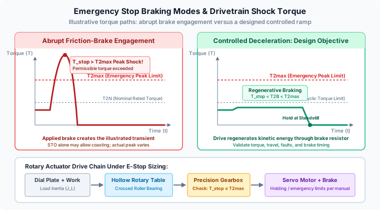
Emergency Stop Deceleration Shock and Holding Brake Sizing in Servo Rotary Actuators: Peak Impact (T2max), Dynamic Braking, and Safe Stop Compliance
Size emergency stop torque and holding brakes for servo rotary actuators. Compare T2max, SS1/STO and braking resistor power; use the engineering RFQ checklist.
2026-W25 Servo Rotary Sourcing: New Compliance Gates & Sizing Safeguards
Week-25 buyer brief for servo hollow rotary tables: EU 12-month sanction extension, USTR forced labor duty proposals, pneumatic air compressor anti-dumping risk, and bore/load sizing rules.